Control Cabinet Layout
Start with functions, not a list of parts
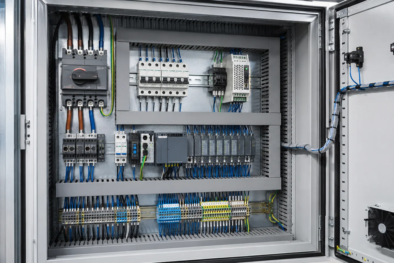
A weak cabinet layout often begins with the question, “Where can this component fit?” A stronger layout begins with the functions that must be understood during installation, testing and maintenance. Incoming supply, main isolation, branch protection, power conversion, control distribution, switching, I/O and field terminals each need their own visible place.
This matters because technicians do not diagnose a panel by reading a parts list. They follow energy and signals. If the isolator is hidden behind cable bundles, if the 24 V DC distribution is split without a clear reason, or if field terminals are mixed with internal wiring, the fault path becomes slower and less reliable.
The cabinet should also leave space for hands, labels, wire markers, ferrules, replacement tools, heat movement and maintenance inspection. A layout that looks full on day one usually becomes worse after site cables, commissioning changes and repair work are carried out.
What should be visible when the door opens
| Cabinet area | What the layout must make clear |
|---|---|
| Supply entry | Where energy enters, which conductors are live before isolation, and where the protective earth path is bonded. |
| Main isolation | The boundary used for service work and the relationship between the door handle, isolator and downstream devices. |
| Branch protection | Which fuses, breakers or protective devices feed each load, power supply or control group. |
| Power conversion | Where AC is converted to 24 V DC or another control voltage, and where the distribution leaves that device. |
| Logic and switching | Where PLC, relay, contactor and interface devices sit in relation to the circuits they control. |
| Field interface | Where external cables terminate, how terminals are numbered and how the cable schedule is followed. |
A practical reading order for cabinet layout
Separate power, control and field wiring by purpose
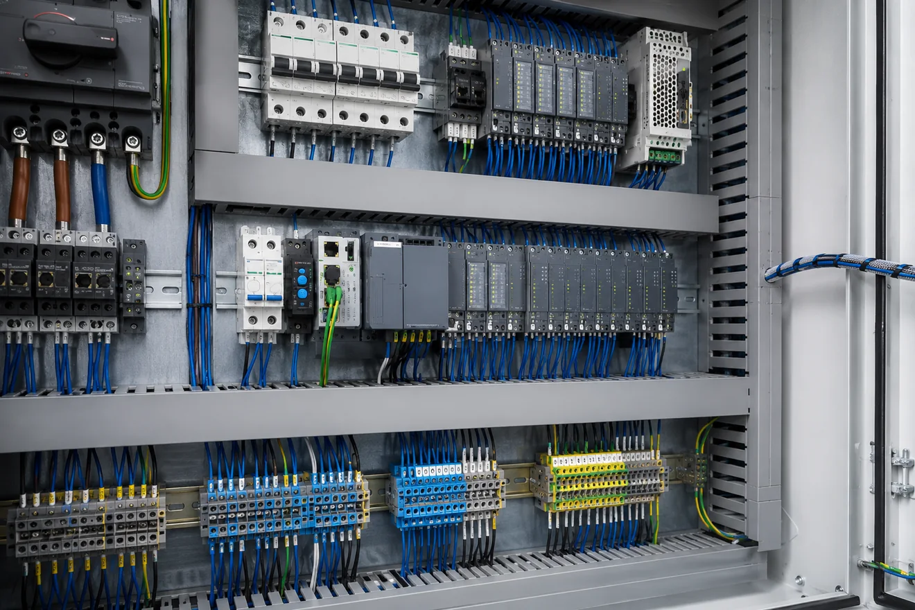
Power wiring, 24 V DC control wiring, safety circuits, analogue signals, communication cables and field cables do different jobs. The layout should make those jobs visible. This does not mean every conductor needs a separate duct, but it does mean the cabinet should not force unrelated circuits into the same congested route.
Higher energy devices such as isolators, motor protection, contactors and drives usually need more attention to creepage, clearance, cable bend radius, heat and service access. PLC modules, signal isolators and communication components need clean wiring routes, readable labels and protection from unnecessary heat and noise.
Where different wiring groups must cross, the crossing should be short and obvious. Long parallel runs between power conductors and sensitive signal cables should be avoided where the project standard requires separation. The goal is not decorative symmetry. The goal is a layout that can be inspected, tested and maintained without guessing.
| Wiring group | Layout priority | Common mistake |
|---|---|---|
| Incoming power | Clear route from cable entry to isolation and protection. | Incoming conductors hidden behind control wiring or trunking. |
| 24 V DC control | Readable distribution from power supply to loads and I/O. | Multiple unlabelled take-off points from the same rail. |
| Analogue signals | Short, identifiable routes with shield handling visible. | Signal wires bundled with contactor or drive wiring. |
| Safety circuits | Traceable path between devices, relays, contacts and reset points. | Safety wiring mixed into general control wiring without clear marking. |
| Field wiring | Terminals close to cable entry and arranged to match the drawing. | External cables landed directly on devices instead of a clear terminal interface. |
Terminal blocks should be designed as the field interface
Terminal blocks are not only a place to join wires. They are the boundary between the built cabinet and the machine, skid, conveyor, pump set or external installation. A strong layout treats terminal blocks as a readable interface, not as spare space at the bottom of the panel.
The terminal strip should tell a logical story. It may follow cable numbers, machine zones, motor groups, instrument loops, I/O card order or a site standard. What matters is that the terminal order is easy to compare with the drawing and cable schedule.
Leave enough room for site cable bend radius, shield termination, earth conductors, wire markers, test access and component replacement. A crowded terminal strip can look acceptable before site wiring arrives, then become the hardest part of the cabinet to inspect.
Checks before the layout is frozen
| Question | Why it matters |
|---|---|
| Can the terminal number be read after field wires are installed? | Labels that disappear under cable bundles slow down commissioning and maintenance. |
| Does terminal order match the drawing or cable schedule? | A logical order reduces wrong landings and makes fault tracing easier. |
| Are PE, shield and screen termination points visible? | Hidden bonding or screen points create inspection problems and can mask installation errors. |
| Is there space for trunking covers and ferrules? | A layout that only works with covers removed is not a serviceable layout. |
| Are spare terminals grouped and labelled? | Unmarked spare points are often misread during panel changes. |
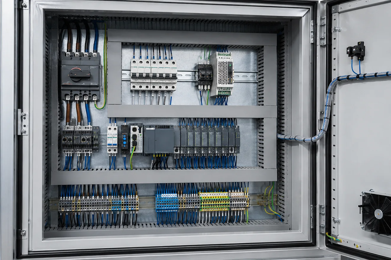
Heat must be allowed for in the layout
Control cabinets are often judged by wiring neatness, but heat is just as important. Power supplies, contactors, drives, braking resistors, dense electronic modules and closely packed protection devices can raise local temperature. Heat does not spread evenly across a backplate, so component grouping matters.
Heat-producing devices need space around them according to their manufacturer data and the enclosure design. Crowding a power supply beside another hot device may not fail immediately, but it can shorten service life and create intermittent faults that appear only during warm operation.
Thermal layout also affects the location of sensitive electronics. PLC modules, communication equipment and analogue signal devices should not be placed where they receive unnecessary heat from drives, transformers or dense power devices. The layout should leave a visible path for air movement, inspection and cleaning.
Component placement matrix
| Component group | Good placement logic | Inspection risk if placed poorly |
|---|---|---|
| Main switch or isolator | Near supply entry, mechanically aligned with door operation where required, and clearly separated from downstream circuits. | The service boundary becomes hard to identify and upstream live parts may be misread. |
| Fuses and circuit breakers | Grouped by feeder or function, with labels visible and downstream wiring easy to follow. | Technicians may remove or test the wrong branch during fault-finding. |
| 24 V DC power supply | Close to control distribution, with heat clearance and a readable DC output path. | Voltage drop, overheating and unclear DC branching become harder to diagnose. |
| PLC and I/O modules | Placed where module labels, field wiring and communication ports remain accessible. | Signal tracing becomes slow and online work may be blocked by cable congestion. |
| Relays and contactors | Grouped by machine function or load group, with coil and contact wiring easy to identify. | Control and load wiring become mixed, which increases tracing errors. |
| Analogue and communication devices | Away from unnecessary heat and high-energy switching routes, with shield and screen handling visible. | Noise, hidden shield problems and unclear signal references become more likely. |
| Terminal blocks | Near field cable entry and ordered by cable, drawing, I/O group or machine area. | Site wiring hides labels and makes documented additions difficult. |
Layout defects seen during inspection
| Defect | Why it causes trouble |
|---|---|
| No visible functional zones | The cabinet cannot be read quickly from supply to field wiring. |
| Overfilled wiring duct | Labels, ferrules and conductors become hard to inspect without disturbing wiring. |
| Hot devices grouped together | Local heat rises and intermittent faults may appear under load. |
| Terminal strip too close to cable entry | Field wiring bend radius and marker visibility suffer after installation. |
| PLC hidden by trunking or relays | Status LEDs, connectors and module labels become hard to read. |
| Uncontrolled spare space | Undocumented changes are squeezed into the nearest gap instead of a readable zone. |
Inspection sequence before a panel is built
A layout review should happen before drilling, cutting wire or fixing trunking permanently. At that stage, mistakes are still cheap to correct. Once the backplate is drilled and the wire duct is full, even small corrections can become slow.
Review the layout against the schematic, cable schedule, heat-producing devices, access needs and expected service tasks. Check whether a person can follow the supply path without removing unrelated covers. Check whether a field cable can be terminated without covering labels. Check whether a hot component has clearances that still exist after wire duct and neighbouring devices are installed.
The best review is practical. Ask what the next person must see first during a fault: incoming voltage, isolator position, branch protection, 24 V DC output, PLC status, relay state, terminal number or field cable. The cabinet layout should make that first check obvious.
Layout checklist
Common Questions
What is the best starting point for control cabinet layout?
Start with function, not component count. Define incoming supply, isolation, protection, power conversion, control power, switching, I/O and field terminals before placing devices on the backplate.
Should power wiring and control wiring share the same duct?
They should normally be separated by function and voltage level according to the project standard. Where different wiring groups must cross, keep the crossing short, clear and easy to inspect.
Where should terminal blocks be placed in a cabinet?
Field terminal blocks should be near cable entry and arranged in a logical order that matches the drawing, machine area or cable schedule. They should remain reachable after trunking covers and device wiring are installed.
Why does heat matter in cabinet layout?
Power supplies, drives, contactors and dense electronics create heat. Crowding them can raise internal temperature, shorten component life and make fault patterns harder to interpret.
Is a neat cabinet always a good cabinet?
No. Neat wiring helps, but layout must also support isolation, protection, heat movement, labelling, measurement access and safe maintenance.
How much spare space should a cabinet layout leave?
Leave usable spare space where additional terminals, branch protection or control devices are expected by the design. Spare space should remain reachable and labelled, not hidden in a corner that cannot be wired cleanly later.