
Control Cabinets: Power, Isolation and Protection
Read the Circuit Before the Label
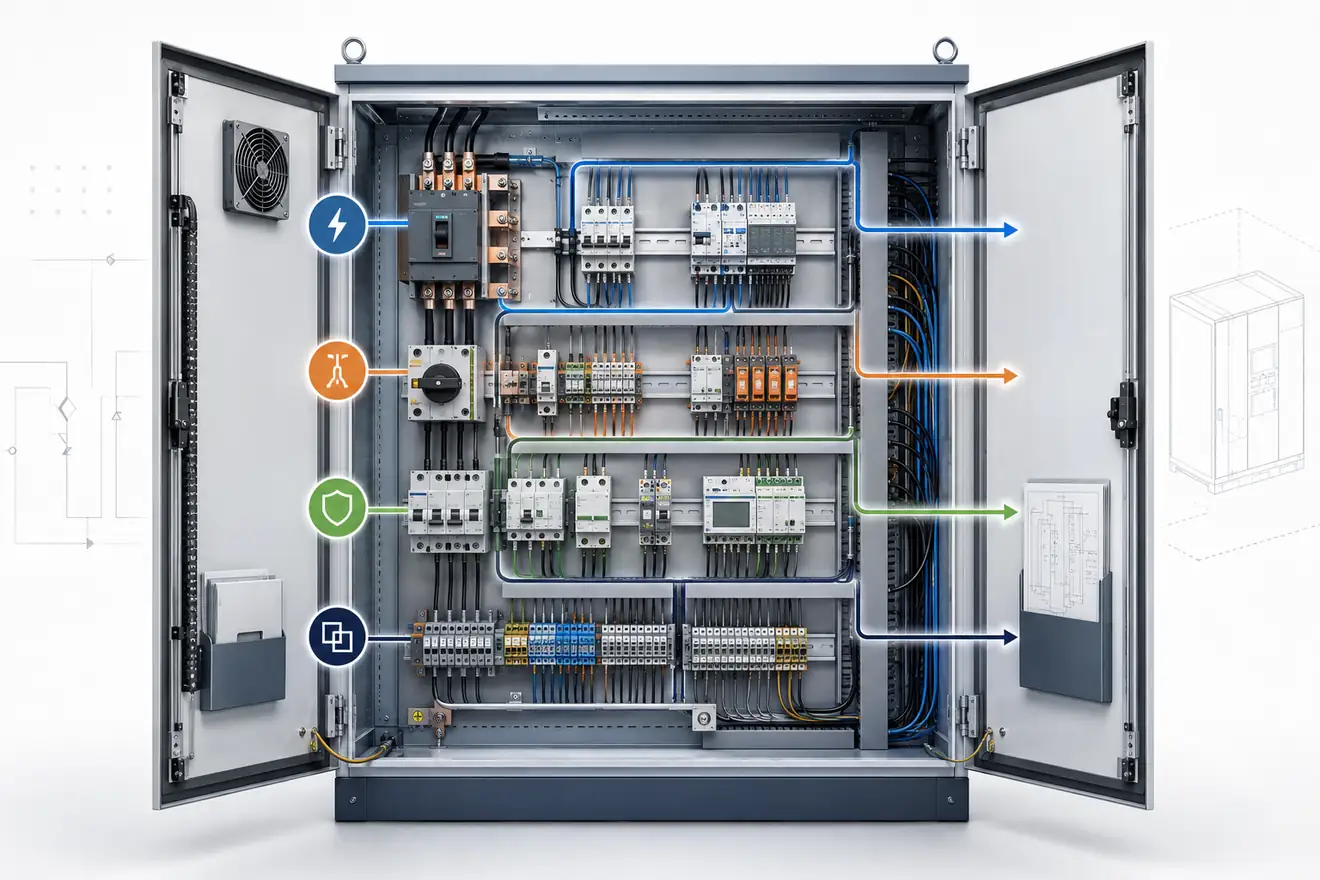
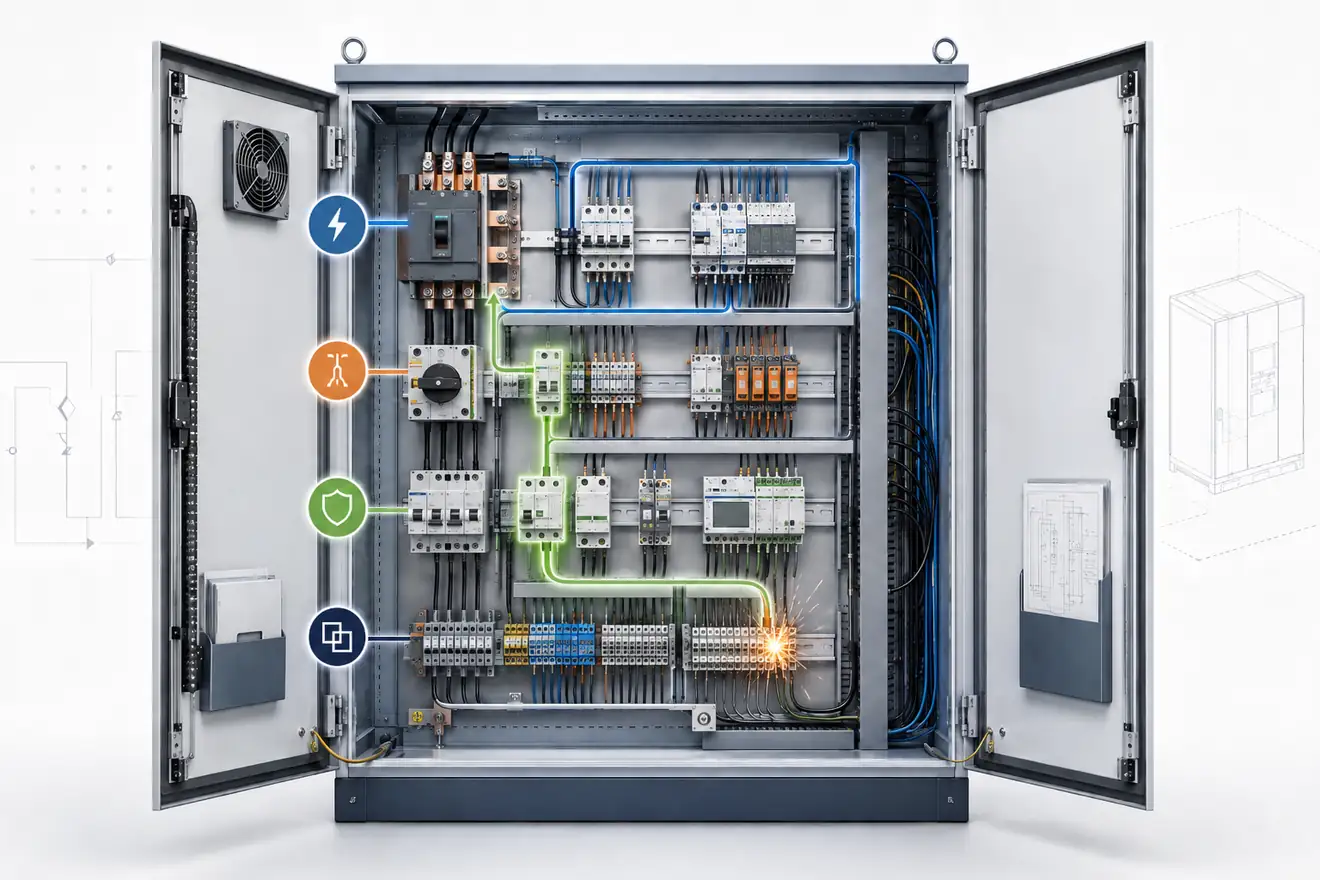
A control cabinet can look complicated because many devices sit close together. The underlying order is usually simpler. Energy enters the enclosure, is divided into branches, passes through switching and protective devices, and leaves through terminals toward sensors, actuators, motors, heaters or other field equipment.
That order matters because many cabinet faults are symptoms, not isolated events. A blown fuse, a tripped breaker, a darkened terminal or an unstable 24 V rail may point to overload, poor cooling, loose connections, voltage drop, inrush current or a load that has changed over time.
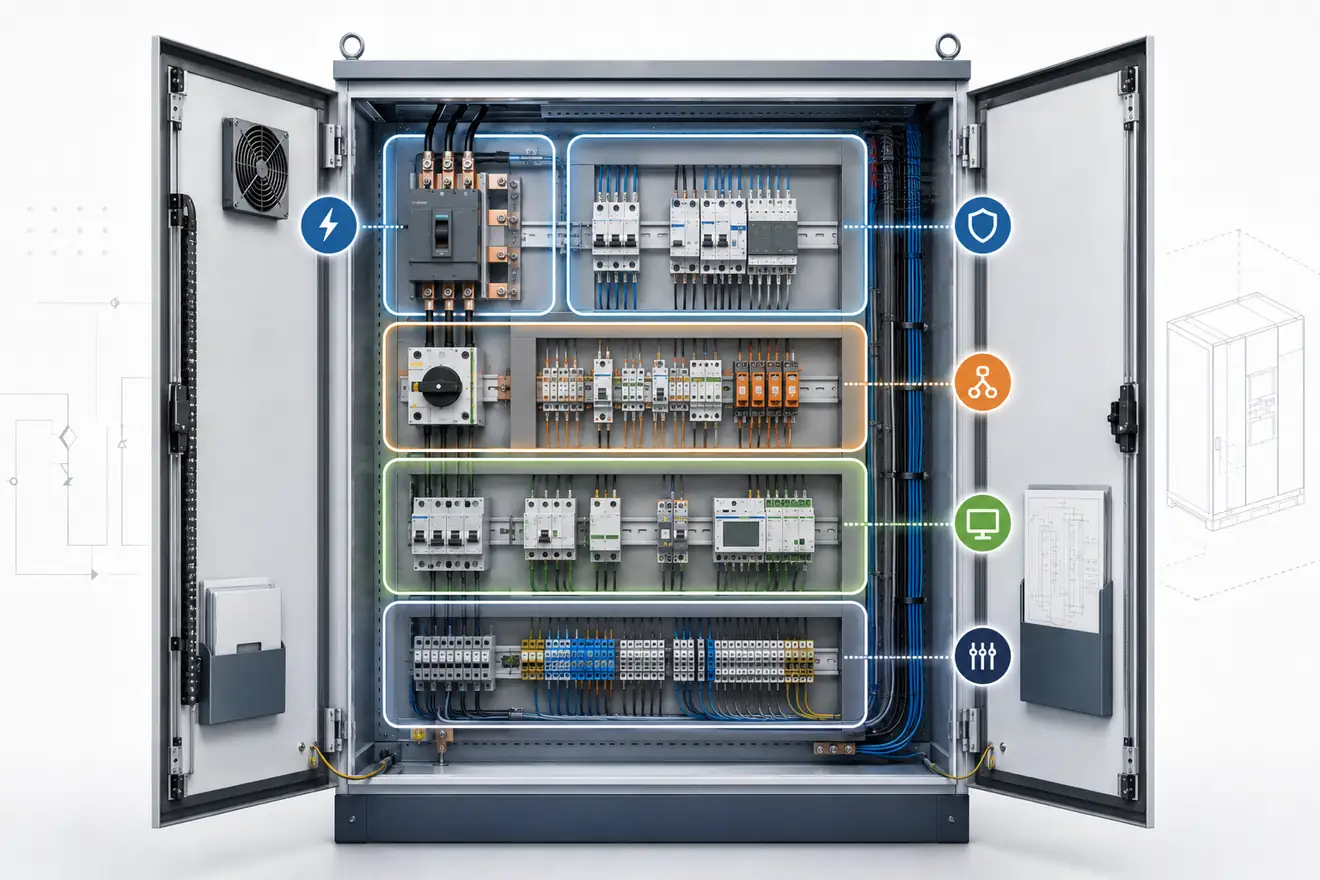
This library keeps the main subjects separate for that reason. Power explains how the cabinet is fed and distributed. Isolation explains the boundary for safe work. Protection explains how fault energy is limited. Engineering covers the wider conditions that influence all three.
Main Sections
Power
Incoming supply, DIN rail supplies, 24 V DC distribution, backup modules, voltage drop and load behaviour.
Open sectionIsolation
Main switches, isolators, load-break switches, door interlocks, lockable off positions and service boundaries.
Open sectionProtection
Fuses, circuit breakers, overload devices, short circuits, repeated trips and visible heat damage.
Open sectionEngineering
Cabinet layout, wiring routes, terminal access, labels, cooling, inspection sequence and conditions that affect the whole panel.
Open sectionHow the Cabinet Functions Work Together
The incoming supply defines the electrical conditions for everything downstream. It sets the voltage system, available fault current, earthing arrangement, cable loading and the reserve capacity available for documented load growth. If this first part of the path is not understood, later device comparisons can look correct while the cabinet still remains poorly matched to the real duty.
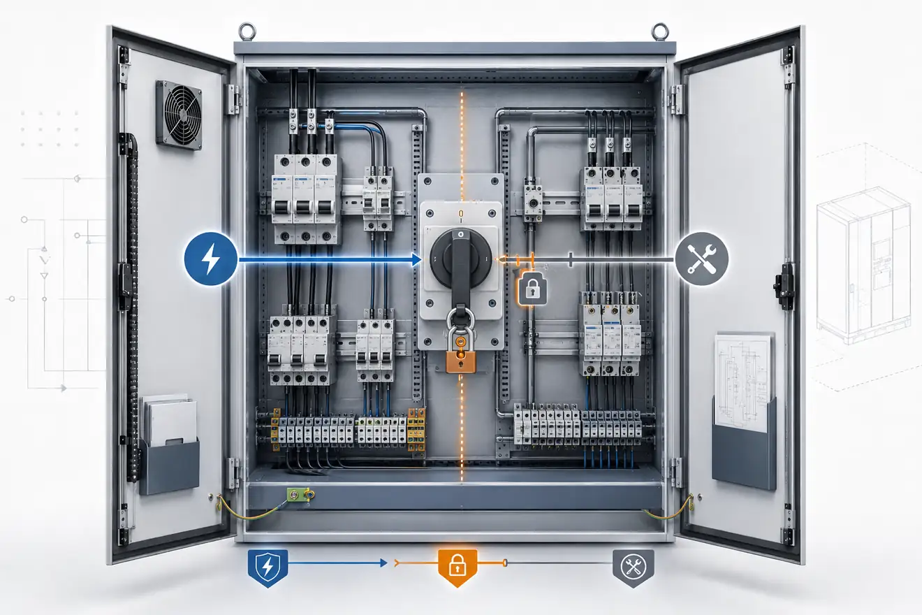
Isolation then defines the boundary for work. A switch may stop a load, but that does not always mean the whole work area is safely separated from energy. A clear inspection should identify what is disconnected, what may remain live, how the off position is secured, and whether the person working on the cabinet can understand the boundary without guesswork.
Protection deals with abnormal current. It is not only a question of amp rating. The protective device has to match the cable, the load, the prospective fault level, the switching duty and the expected behaviour during starting or inrush. When protection is selected without this context, nuisance operation and hidden overheating become more likely.
Engineering ties these checks together. Layout, ventilation, terminal access, labelling and cable routing decide how easy it is to inspect the cabinet and how quickly early signs of failure are noticed. A cabinet that is easy to read is usually easier to maintain, even when the equipment inside is technically complex.
From supply to condition
A useful review begins at the supply and follows the path toward the load. The aim is to connect each device to its duty: feeding, disconnecting, protecting, switching, signalling or terminating.
After the path is understood, the physical condition matters. Heat marks, loose conductors, discoloured insulation, crowded wiring and unclear labels are not cosmetic details. They are evidence about stress inside the cabinet.
Evidence Before Replacement
| Evidence | What it may indicate |
|---|---|
| Low control voltage | Load growth, voltage drop, overloaded supply, weak terminals or thermal derating. |
| Unclear off state | A switching device may not define the full isolation boundary for safe work. |
| Repeated operation of a protective device | Overload, inrush, short circuit, wrong device duty, poor selectivity or a changing load. |
| Heat marks or discoloured insulation | Loose pressure, excessive current, restricted ventilation, poor spacing or ageing conductors. |
The Cause Has to Match the Symptom
Replacing the visible failed item may restore operation for a short time, but it does not prove that the cause has been removed. A protective device may have opened because the downstream load is failing. A terminal may be dark because of contact pressure, heat, conductor size or repeated overload. A power supply may appear weak because the connected load has grown beyond the original design.
A better inspection separates evidence from assumption. Voltage, temperature, contact condition, cable route, load behaviour and the history of repeated faults all matter. This does not make the cabinet more difficult to understand. It gives the inspection a clean order.
The useful question is not only what failed, but whether the surrounding conditions still make the same failure likely. When this question is answered first, replacement becomes part of a repair process rather than a repeated guess.
What a Good Cabinet Check Should Prove
First Reading Path
24 V DC Power Supply
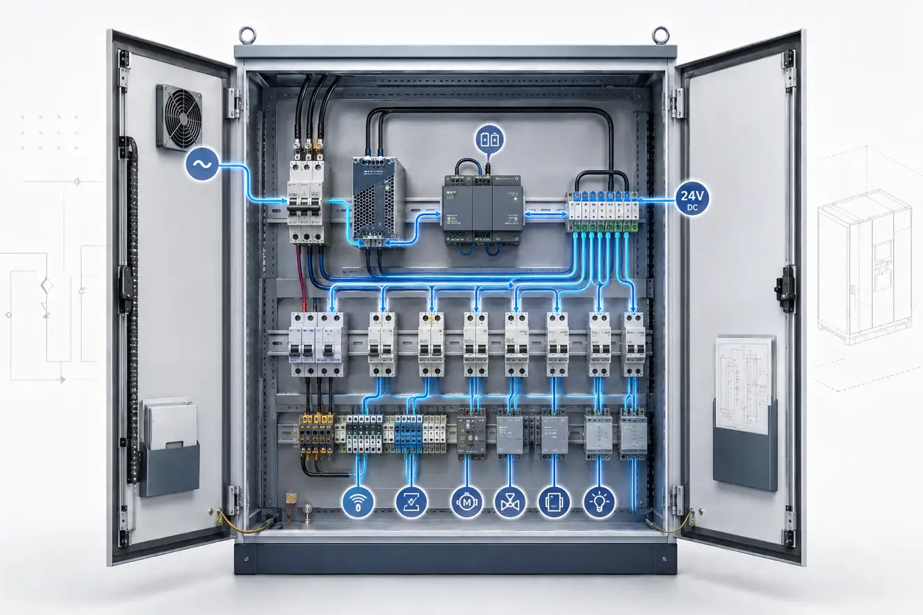
Follow the control voltage from the supply output to the real loads, including voltage drop, load current and unstable devices.
Read pageMain Switch vs Isolator
Understand the difference between ordinary switching and a clear off state for service work.
Read pageFuse vs Circuit Breaker
Compare fuses and breakers by the circuit they protect, the fault they must clear and the evidence left after operation.
Read pageControl Cabinet Layout
Read the panel by zones: incoming power, protection, control power, terminals, wiring routes and heat.
Read page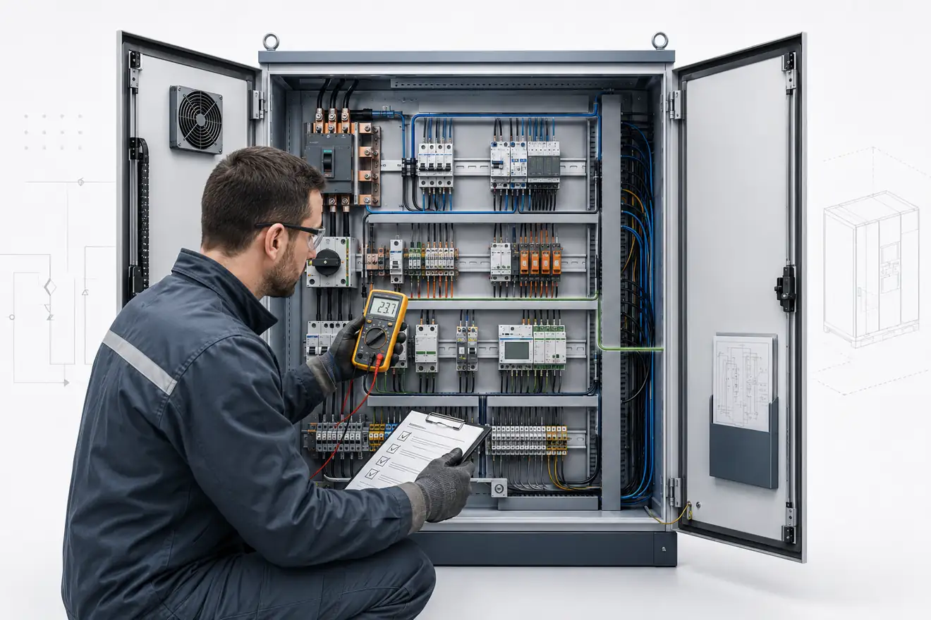
A Clearer Way to Read the Cabinet
If the cabinet has unstable control voltage, start with Power. If the safe off state is unclear, start with Isolation. If the cabinet keeps tripping or a holder is damaged, start with Protection. If the problem is hard access, heat, wiring route or poor labels, start with Engineering.
This order keeps related evidence together. Voltage drop belongs to the power path. A door interlock belongs to the isolation boundary. A damaged fuse holder belongs to protection, but the reason may also involve heat, terminal pressure, load duty or cabinet layout.
Repeated faults should therefore be treated as evidence of a condition, not only as a request for another part. A stable repair normally starts by proving the supply, boundary, protective path, load behaviour and physical condition in the same order each time.
Common Questions
What is a control cabinet?
It is an enclosure that brings together equipment used to feed, switch, protect and control a machine or process.
Where should a cabinet check begin?
Begin with the job of the circuit. Then follow supply, isolation, protection, load, wiring and visible condition.
Why separate power, isolation and protection?
They solve different problems. Power feeds the cabinet, isolation creates a safe off state, and protection limits fault energy.
What belongs in Engineering?
Engineering covers wider cabinet subjects such as layout, terminals, wiring routes, heat, markings and inspection order.
Why can a new part fail again?
The original cause may still be present: overload, poor cooling, loose wiring, repeated starting, low voltage or damage outside the cabinet.
Why does cabinet layout matter?
Layout affects heat, access, cable routing, labels and how quickly the circuit path can be followed during inspection.