Control Cabinet Engineering Library
What the Cabinet Layout Must Prove
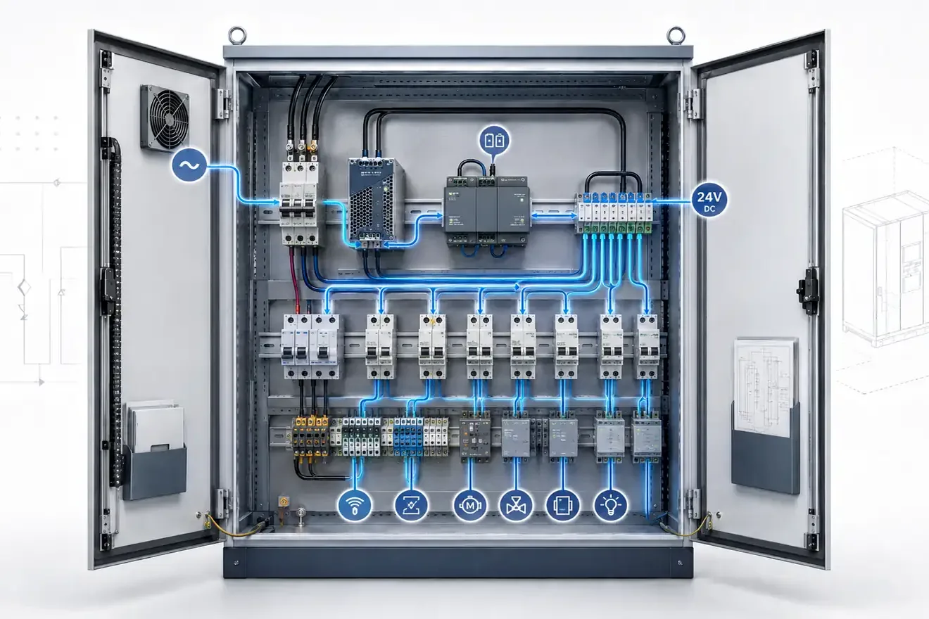
A control cabinet can contain correct components and still be difficult to inspect. The layout must make the circuit path readable, keep terminals accessible, separate functions clearly and allow heat to leave the enclosure.
Good engineering is visible before a meter is connected. Incoming supply, isolation, protection, control wiring and field terminals should be arranged so that a fault can be followed in a logical order.
The practical question is whether another competent person can identify the circuit path, inspect the terminals and understand the function without guessing from cable colour or device position alone.
Engineering Library
Control Cabinet Layout
Read the cabinet as one working system: power areas, isolation point, protective devices, control wiring, terminals, heat and access.
Read pageControl Cabinet Wire Routing
Follow power, control, signal and field wiring through the cabinet so routes stay readable, serviceable and easier to inspect.
Read pageVFD Overvoltage Fault
Diagnose overvoltage during deceleration, DC bus rise, brake chopper use and braking resistor checks before ordering.
Read pageVFD Cable Shield Grounding
Ground motor, control and encoder cable shields with 360° termination, local disconnect checks and clear PE, FE and 0 V boundaries.
Read pageTypical Engineering Fault Evidence
Many cabinet problems appear as failed devices but start as physical conditions. Tight wiring can stress terminals, poor ventilation can accelerate ageing, and unclear labels can make a simple inspection unsafe or slow.
Evidence should be read in order: conductor route, terminal pressure, heat marks, enclosure temperature, cable bend radius, device spacing, label clarity and access for measurement. A component fault is more convincing when the surrounding conditions also make sense.
Engineering Checks by Function
| Function | What to check | Common evidence |
|---|---|---|
| Layout | Separation of power, control, protection and field wiring areas. | Hard-to-follow circuit path, crowded devices, unclear service boundary. |
| Wiring routes | Cable duct fill, bend radius, conductor support and route visibility. | Stressed wires, hidden damage, trapped heat, difficult voltage checks. |
| Terminals | Access for inspection, pressure marks, numbering and heat condition. | Loose conductors, discoloration, intermittent faults, repeated retightening. |
| Cabinet heat | Device spacing, ventilation path, fan condition and heat-producing loads. | Warm supply units, aged plastic, nuisance trips, drifting electronics. |
Common Questions
What should be checked first when reading a cabinet layout?
Start with the physical circuit path: incoming conductors, isolation point, protective devices, control wiring, terminal rows, heat sources and service access.
Why do wiring routes and cabinet heat matter?
Poor wiring routes can hide damaged conductors or make voltage checks difficult, while heat can affect terminals, power supplies, contactors, protective devices and electronic modules.