Control Cabinet Wire Routing
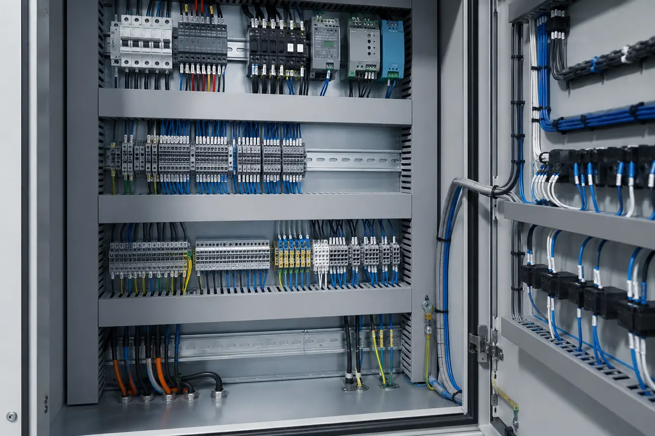
Route Conductors by Function Before They Enter the Duct
Power conductors, 24 V DC control wiring, analogue signals, safety circuits, communications and field cables do not all need the same route. They carry different energy levels, react differently to noise and heat, and are checked in different ways during commissioning or fault-finding.
A good layout makes those differences visible. Higher-energy conductors should not force sensitive wiring into the same congested path. Control wiring should leave the power supply and distribution area in a way that can be followed without guessing. Field wiring should arrive at terminal blocks in an order that matches the drawing, cable schedule or machine area.
The aim is not decorative symmetry. The aim is a cabinet where a technician can open the door, follow the circuit, read the marker, remove a duct cover and reach the terminal without disturbing unrelated wiring.
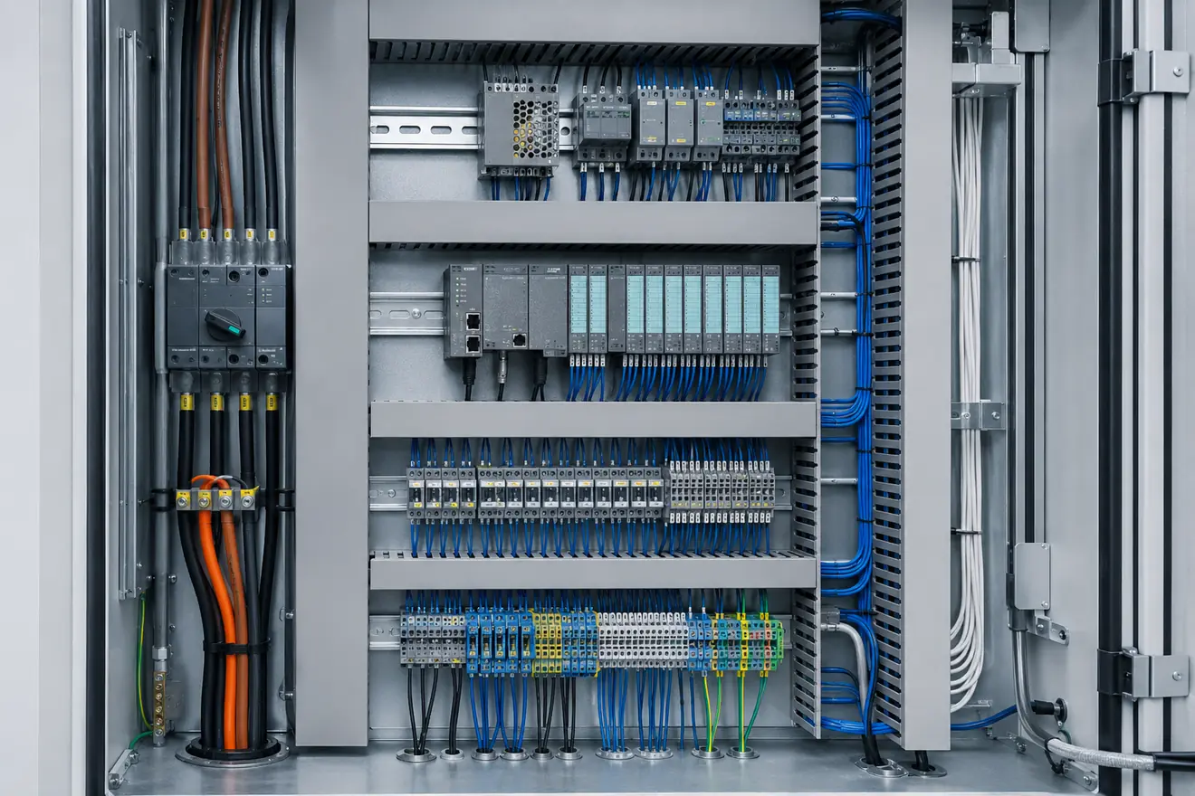
Wiring Groups Need Different Layout Priorities
| Wiring group | Good routing logic | Risk when routed poorly |
|---|---|---|
| Incoming and load power | Short, protected and easy to follow from entry through isolation and branch protection. | High-energy paths become hidden behind control wiring or unrelated terminal groups. |
| 24 V DC control | Clear path from supply output to distribution, I/O, relays and control loads. | Voltage drop and overloaded branches become harder to find. |
| Analogue signals | Kept away from unnecessary switching noise, heat and long parallel runs with power conductors. | Unstable readings may be blamed on the instrument before the route is checked. |
| Safety circuits | Traceable between devices, contacts, reset points and safety relays. | The safety function becomes difficult to verify visually during inspection. |
| Communication cables | Accessible ports and clean routes that avoid tight bends and avoidable interference. | Service access and network fault checks become slow. |
| Field wiring | Landed at terminals in cable, drawing or machine-zone order. | Site cables can hide labels and make maintenance access untidy. |
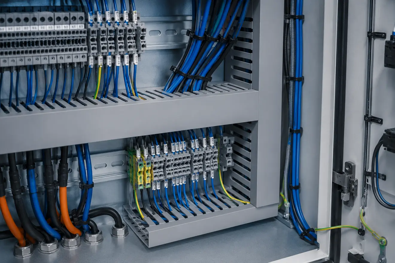
Wire Duct Capacity Is a Serviceability Issue
Wire duct gives the cabinet a clean path, but it should not be treated as unlimited storage. When a duct is packed tightly, labels disappear, ferrules become difficult to see, and a simple tracing job may require moving conductors that should not be disturbed.
Capacity also affects service work. A panel often receives replacement devices, extra terminals or documented wiring changes during its life. If every route is full at build stage, additional wiring is pushed into the nearest gap instead of a readable path.
Good routing leaves space where changes are most likely: near field terminals, around 24 V distribution, close to spare I/O, and beside devices that may be replaced. The spare space should be usable, not just an empty corner that cannot be wired cleanly.
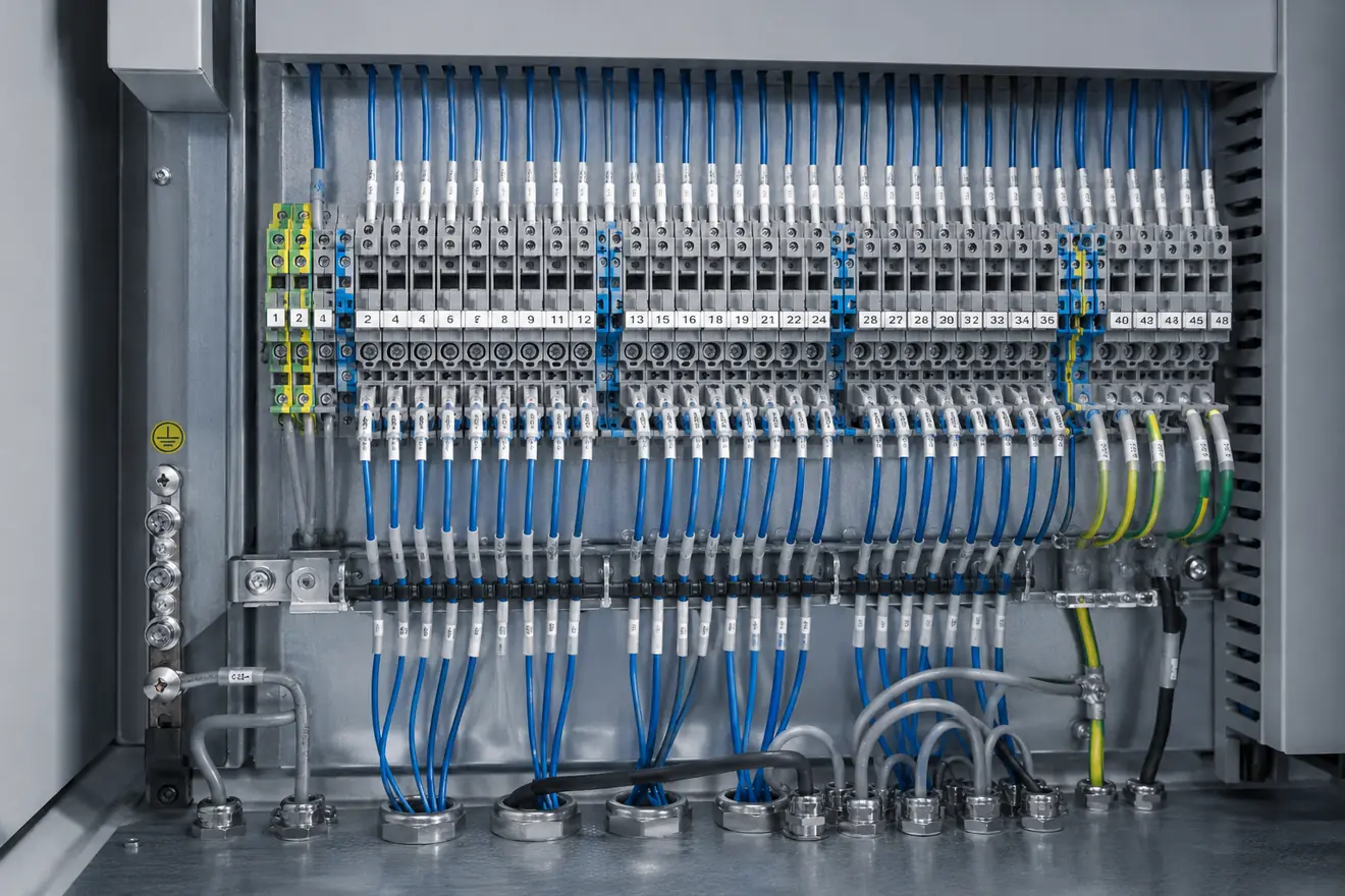
Terminals Are the Boundary Between Cabinet and Field
Field cables should not turn the cabinet into a knot of direct device connections. A clear terminal interface gives the external installation a defined landing point and gives the technician a place to test, disconnect, label and compare with the cable schedule.
Terminal order may follow cable number, machine zone, instrument loop, motor group or I/O card order. The chosen logic matters less than its consistency. When the terminal strip matches the drawing order, the first inspection is faster and wrong landings are easier to catch.
Shield and PE conductors need the same clarity. Earth terminals, screen clamps and bonding points should remain visible after field cables arrive. Hidden shield treatment often creates noise complaints that are difficult to separate from instrument or input-card faults.
Checks Before the Wiring Route Is Frozen
Wiring Problems That Look Like Device Faults
| Symptom | Wiring condition to check |
|---|---|
| Unstable analogue value | Long parallel path with power wiring, unclear shield termination or hidden loose terminal. |
| Repeated 24 V dips | Overloaded distribution branch, long small conductor path or congested common return. |
| Intermittent field input | Terminal pressure, strained field cable, damaged ferrule or hidden splice inside duct. |
| Communication dropout | Tight bend, mixed route with switching conductors, poor screen handling or blocked port access. |
| Heat at terminal group | Loose pressure, excessive load, poor conductor choice or crowded wiring that restricts inspection. |
Inspection Should Not Start by Blaming the Module
A signal fault is often blamed on the sensor, input card or instrument. A control voltage problem is often blamed on the power supply. Sometimes that is correct, but the cabinet wiring should be checked before the conclusion becomes fixed.
Look for the route that the symptom depends on. Does the signal run beside high-energy switching conductors? Is the common return crowded or split in a way that hides voltage drop? Are field wires strained as they leave the duct? Can the terminal number be read without moving cable bundles?
This kind of check does not make the repair slower. It prevents the same fault from returning after a new device is fitted into the same poor wiring condition.
Wire Routing Checklist
Common Questions
What is the purpose of wire routing in a control cabinet?
Wire routing keeps power, control, signal and field conductors readable and serviceable. It helps a technician follow the circuit without moving unrelated wiring or hiding labels.
Should power and signal wiring be routed together?
They should normally be separated by function and voltage level according to the project standard. If different groups cross, the crossing should be short, visible and easy to inspect.
Why does wire duct capacity matter?
A full duct makes ferrules, labels and conductors hard to inspect and can turn a small wiring change into a messy repair. Spare capacity also protects access to covers and terminals.
Where should field cables land?
Field cables should normally land on a clear terminal interface near cable entry, with terminal order matching the drawing, cable schedule or machine area.
How should shield and PE conductors be treated in the layout?
Shield and protective earth paths should be visible, short where required, mechanically secure and easy to compare with the drawing or installation standard.
Is neat wiring enough for a good panel?
No. Neat wiring helps, but the arrangement must also support separation, heat movement, test access, terminal reading, drawing comparison and safe inspection.