24 V DC Electronic Circuit Breakers
Why it is different from a 24 V DC MCB
Miniature circuit breakers and electronic circuit breakers may both appear in a 24 V DC control cabinet, but they work on different assumptions. A conventional MCB relies on a bimetallic thermal element for overloads and a magnetic release for fast short-circuit operation. That fast magnetic release needs enough prospective current at the fault point.
In many low-voltage DC control circuits, that assumption is weak. The power supply limits its output, the field cable adds loop impedance, and the apparent short circuit at the machine may look like a controlled overload at the panel. The breaker is not necessarily faulty; it may simply never see the current needed for fast operation.
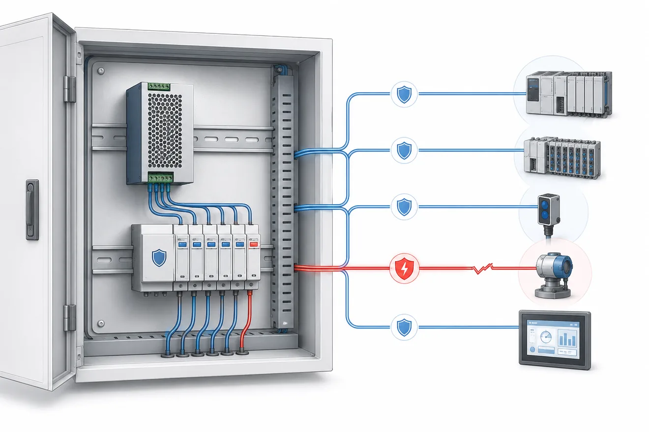
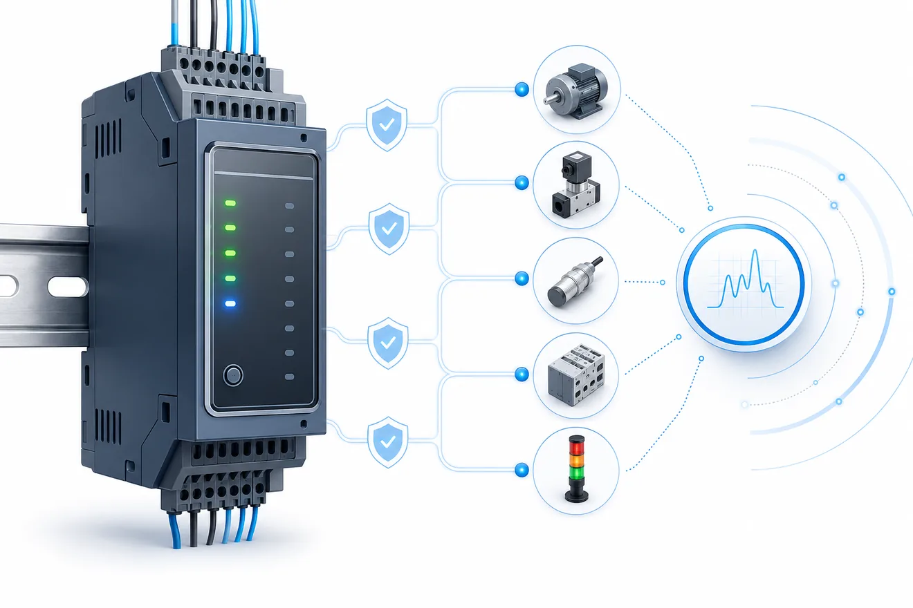
An electronic circuit breaker monitors each protected branch directly and disconnects the channel when its set limit and timing are exceeded. Many modules also provide local LEDs, group alarm contacts, reset inputs or communication options. The important engineering question is therefore not only whether a device can carry 4 A continuously, but whether a local branch fault will clear before the common DC bus falls far enough to reset the PLC, remote I/O or network switch.
Same cabinet, different fault behaviour
| Technical parameter | Standard 24 V DC MCB | Electronic circuit breaker |
|---|---|---|
| Operating principle | Thermal-magnetic mechanical tripping. | Electronic current sensing with solid-state, often MOSFET-based, output switching. |
| Fault current requirement | Needs sufficient prospective current for fast magnetic tripping. | Trips from calibrated channel current and timing thresholds. |
| Interaction with SMPS current limit | May not trip quickly if the supply clamps current first. | Can isolate the affected branch before the shared DC rail collapses. |
| Diagnostics | Usually limited to local handle position or auxiliary contact options. | Often provides LEDs, alarm contacts, reset inputs and module-level status outputs. |
| Reset | Normally manual at the device. | May support manual reset, remote reset or controlled restart logic, depending on the product. |
| Best fit | Branches where fault current and trip time have been verified. | Control-load branches where selectivity, diagnosis and uptime matter. |
What happens during a 24 V DC branch short circuit
Power supply behaviour decides whether the branch clears cleanly
Most industrial control panels use switched-mode power supplies with built-in self-protection. These functions are useful because they prevent the supply from being destroyed by an overload, but they can also prevent a conventional branch breaker from seeing the fault current it needs.
In current-limiting mode, the supply caps output current while the voltage falls. In hiccup mode, it repeatedly switches the output off and on. In fold-back mode, output current and voltage both reduce as the fault remains. Each behaviour protects the supply, but it can also starve a thermal-magnetic MCB of the current required for fast magnetic operation.
For this reason, fitting a 4 A mechanical breaker on a 24 V DC line does not, by itself, prove selective protection. Breaker curve, field-cable impedance, load capacitance, terminal voltage and the supply overload response all have to be considered as one system. Electronic circuit breakers reduce this dependency by making the isolation decision at the protected branch.
Why a C-curve MCB can miss a 24 V DC branch fault
A common design error is to select a miniature circuit breaker by the normal load current and then assume it will clear any downstream short circuit. That only works when the fault loop can deliver the prospective current required by the magnetic trip mechanism.
In a real control cabinet, the available fault current can be restricted before the breaker reaches that region. The power supply clamps its output, the field cable adds resistance, and the voltage at the load collapses. Under those conditions the MCB is not defective; it is being asked to perform a task that the circuit cannot support.
Electronic protection is useful on PLC, I/O and field-instrument branches because it does not rely on a large short-circuit current at the end of a long cable run. It samples the channel current locally and disconnects according to defined electronic thresholds and timing.
What has to be true before relying on an MCB
| Engineering variable | System impact |
|---|---|
| Prospective short-circuit current | A thermal-magnetic breaker needs high peak current for fast magnetic operation. A current-limited SMPS may restrict that current before rapid isolation occurs. |
| Field cable loop impedance | Long cable runs add resistance, so a remote short circuit can appear at the cabinet as a limited overload rather than a high-current fault. |
| Common bus voltage integrity | If the 24 V DC rail sags before the branch clears, healthy PLC processors, I/O modules and communication devices may reset. |
| Transient load capacitance | HMIs, DC-DC converters and electronic modules can draw high start-up current that must not be confused with a fault. |
| Diagnostic granularity | A mechanical breaker gives limited fault context. Electronic protection can identify the affected channel and send a status signal. |
Where electronic circuit breakers are worth using
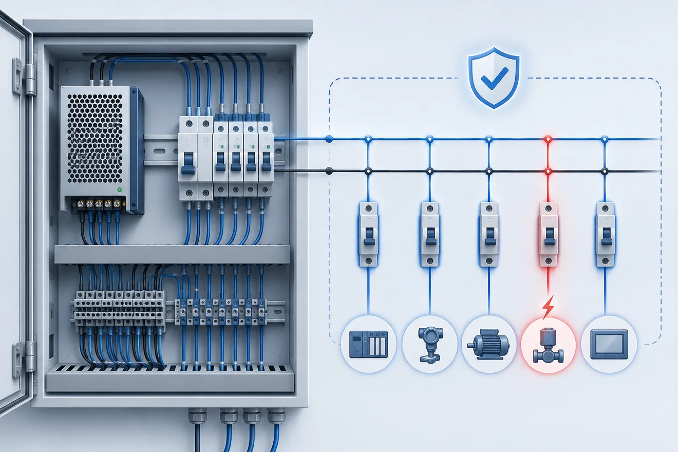
Selective electronic branch protection is most valuable where several important 24 V DC loads share one power source. A local fault on a sensor group, valve island or auxiliary branch should not remove power from the PLC CPU, HMI or main network equipment.
Used well, this changes fault management from a search through a dead panel into a named diagnostic task. Channel LEDs, alarm outputs or communication data can point maintenance staff to the affected circuit while healthy loads remain energised.
Electronic modules should still be used deliberately. The decision should consider machine availability, channel count, likely failure consequence, cabinet space, reset philosophy and how diagnostic status will be used by the control system.
For North American designs, electronic branch protection can also form part of an NEC Class 2 power-limited strategy, but only where the source or protective device is listed or approved for that purpose and the field wiring method matches the design.
Typical 24 V DC loads
| Load group | Benefit of selective isolation |
|---|---|
| PLC CPU and core electronics | Helps keep the central control logic powered when a peripheral branch fails. |
| I/O module assemblies | Keeps healthy I/O groups powered while one protected branch is isolated. |
| Field sensor supplies | Confines cable damage, moisture ingress or connector faults to a named channel. |
| Valve islands and solenoid coils | Limits the effect of coil faults or damaged actuator wiring on the main DC rail. |
| HMI panels and industrial PCs | Reduces nuisance reboots and data-risk events caused by unrelated field faults. |
| Remote I/O stations | Provides status information before a technician has to open the cabinet or inspect the machine area. |
Selection is more than the current setting
A channel threshold set too low will trip on normal inrush from HMIs, I/O nodes, communication devices or DC-DC converters. A threshold set too high can leave field wiring under-protected or allow the shared DC rail to sag before the branch is isolated.
Each protected output should be treated as a defined circuit, not as a spare point on a distribution module. Normal current, start-up current, cable cross-section, voltage drop, terminal rating, ambient temperature and diagnostic needs all influence the correct channel arrangement.
The reset method also matters. Automatic reset can hide a repeating field fault. Manual reset forces cabinet inspection. Remote reset can be useful when it is tied to a controlled sequence and does not restart a dangerous or unstable load without checks.
Selection checklist for a 24 V DC electronic circuit breaker
| Design parameter | What to verify | Common design oversight |
|---|---|---|
| Steady-state branch current | Confirm the total normal current of every load connected to the channel. | Setting the channel from one device nameplate while missing the combined branch load. |
| Transient inrush | Check start-up current from HMIs, I/O stations, converters and capacitive input stages. | Selecting a trip profile that opens during normal power-up. |
| Conductor protection | Check conductor cross-section, insulation rating, terminal rating and installation method. | Treating electronic trip settings as a substitute for correct wire sizing. |
| Voltage drop | Measure or calculate the minimum load voltage on long field runs at maximum demand. | Ignoring cable resistance until sensors or remote modules fall below their operating range. |
| Power supply reserve | Compare the supply overload behaviour and boost capacity with the module trip behaviour. | Using a supply that enters protection before the electronic breaker can isolate the branch cleanly. |
| Circuit grouping | Group loads by function, machine area and fault consequence. | Putting critical control electronics and exposed field wiring on the same protected channel. |
| Status and alarm wiring | Decide whether local LEDs, group contacts, PLC inputs or communication status are needed. | Installing an intelligent module but leaving its diagnostic outputs unused. |
| Reset philosophy | Define manual, remote or automatic reset in the machine sequence. | Allowing repeated automatic restarts on a persistent live fault. |
MCB, fuse or electronic breaker: choose by fault behaviour
| Protection technology | Best use case | Important limitation in 24 V DC systems |
|---|---|---|
| Fuse | Simple, cost-sensitive branches with predictable loads and little need for remote status. | It must be replaced after operation, and weak fault current can still lead to poor selectivity if the system has not been checked. |
| Thermal-magnetic MCB | Branches where the supply, conductor size and loop impedance can deliver enough current for the selected trip curve. | It can be too slow, or may not reach fast trip, when the SMPS clamps current first. |
| Electronic circuit breaker | Automation branches where one fault should be isolated while PLC, I/O, HMI, sensor or network loads remain powered. | It still needs correct conductor checks, channel grouping, inrush allowance, alarm wiring and reset control. |
| Power supply current limit only | Self-protection of the power supply during overload. | It is not branch selectivity. One field fault can remove voltage from every connected load. |
Faults that electronic protection can localise
| Field failure mode | Electronic protection response |
|---|---|
| Moisture ingress in a field connector | Isolates the affected sensor supply while keeping PLC and healthy field nodes powered. |
| Insulation breakdown in a solenoid coil | Disconnects the actuator branch before the fault drags down the main 24 V DC rail. |
| Conductor pinched on the machine frame | Identifies the protected channel involved, reducing the search area during maintenance. |
| High-capacitance HMI start-up | Allows normal inrush when the module and profile are selected correctly, while still reacting to sustained faults. |
| Overload on remote I/O | Sends a status indication before the fault becomes a general control-power failure. |
| Intermittent short circuit | Can expose repeat channel trips that would otherwise look like random power-supply resets. |
What electronic protection does not solve
Electronic circuit breakers improve 24 V DC selectivity, but they do not repair a weak electrical design. They cannot compensate for an undersized power supply, poor conductor sizing, excessive voltage drop, unsuitable terminal ratings or missing documentation.
Channel grouping needs discipline. A four-channel module loses much of its value if each output feeds a random mix of PLC power, field sensors, valve coils and auxiliary devices. Each protected branch should map to a circuit that is visible in the schematic, terminal labels and fault message.
NEC Class 2 design also needs care. Setting a channel to 4 A does not automatically create a Class 2 circuit. The source or protective device must be evaluated for the required power-limited function, and the wiring method must follow the applicable design rules.