VFD Overvoltage Fault and Braking Resistor Sizing
Start With the Moment of the Fault
| When the trip appears | Most likely direction | First useful check | Typical next step |
|---|---|---|---|
| At power-up or idle | Incoming supply, DC bus threshold, drive settings or line disturbance. | Measure supply voltage and compare the fault history with machine state. | Correct supply issue, transformer tap or drive parameter before adding brake hardware. |
| At steady speed | Overhauling load, unstable supply, line regeneration or a load pushing the motor. | Check whether the load can drive the motor mechanically. | Review load behaviour and drive mode; braking parts may not be the first fix. |
| During deceleration | Regenerated energy raises the DC bus during a fast stop. | Increase decel time temporarily and watch whether the trip disappears. | If the stop time cannot be extended, check brake chopper and resistor sizing. |
| During emergency or quick stop | Stop demand is higher than the drive and existing braking path can absorb. | Compare required stop profile with the drive manual and safety design. | Use suitable braking hardware or a different stopping method. |
| After a resistor was fitted | Wrong resistance, wrong duty rating, missing chopper, thermal trip or wiring issue. | Check resistance against the drive minimum and check resistor temperature protection. | Correct the package instead of simply fitting a larger-looking resistor. |
What Happens During a Fast Stop
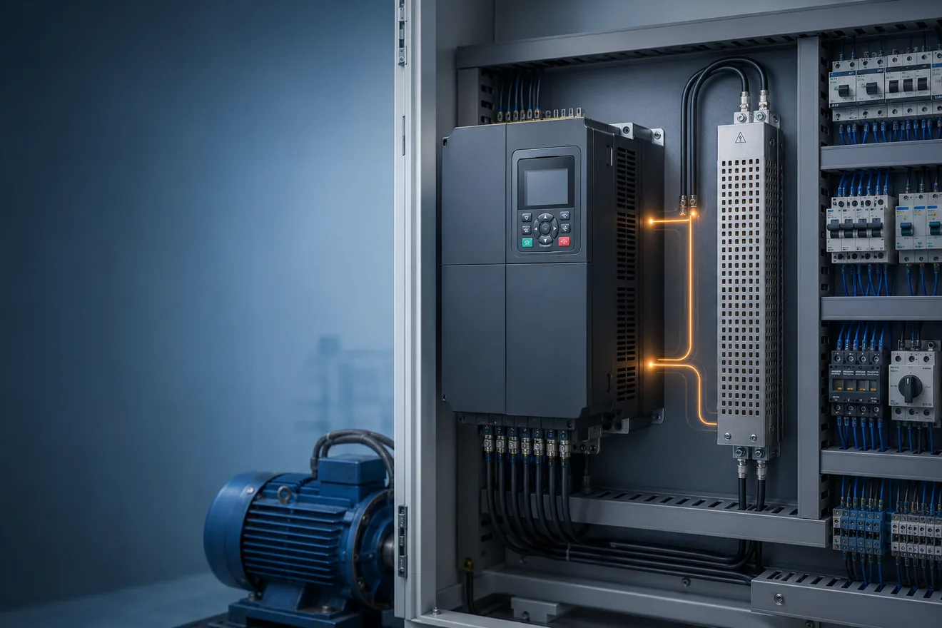
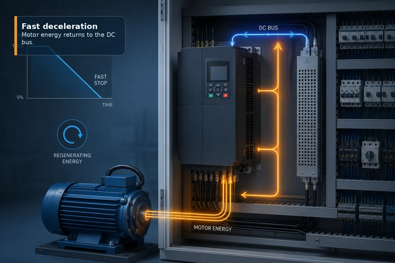
A VFD normally rectifies the incoming AC supply into a DC bus, then uses the inverter section to control the motor. During a hard stop, a motor connected to a heavy or overhauling load can act like a generator. The returned energy raises the DC bus voltage.
If the drive cannot absorb or remove that energy quickly enough, it trips on overvoltage to protect itself. Extending the deceleration time often proves the point: the same load stops more slowly and the bus has less energy to absorb at once.
This is why the first repair should not be guesswork. A braking resistor may be correct for a fast repeated stop, but it is not the answer to every overvoltage code.
Brake Chopper and Resistor Are Not the Same Part
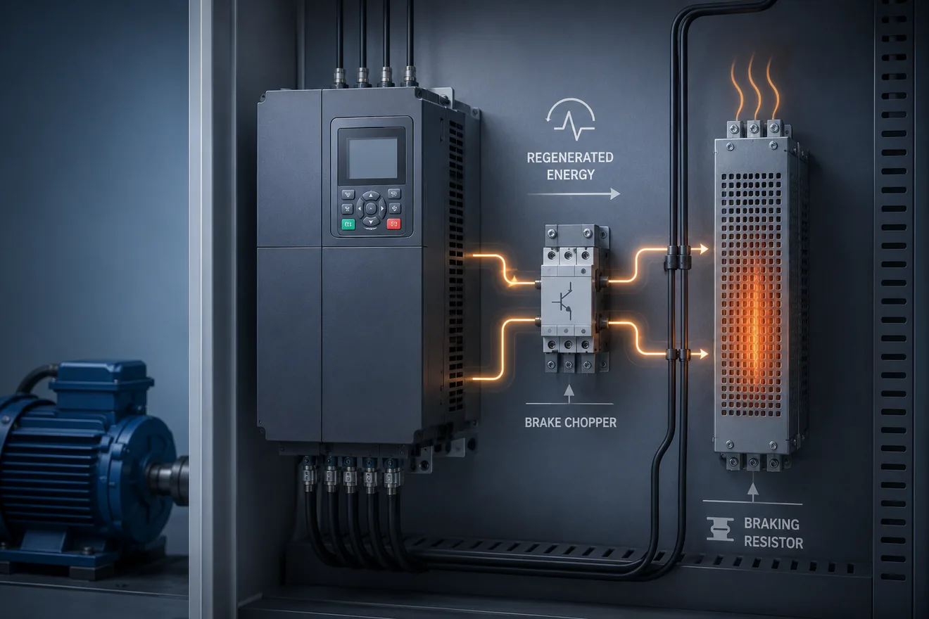
The resistor is only the place where braking energy becomes heat. The chopper circuit, braking transistor or external braking unit decides when that path is connected to the DC bus.
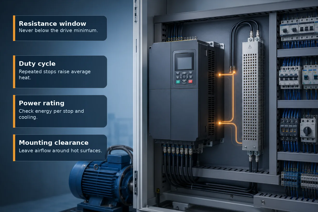
Before sizing the resistor, confirm whether the drive has an internal brake transistor, whether it needs an external braking unit, and what minimum resistance the manufacturer allows. A resistor below that minimum can pull too much current through the braking device.
The power rating is a separate question. It depends on how much energy is produced during each stop and how often that stop repeats. A resistor that survives one stop may still overheat in a short cycle.
Quick Braking Resistor Screening
The calculator below is deliberately conservative and simple. It helps decide whether the job is light, moderate or likely to need a proper braking package. Final resistance, wattage, thermal protection and mounting must come from the drive manual and resistor data.
Use it when the fault happens during deceleration and the machine cannot simply stop more slowly. For hoists, centrifuges, downhill conveyors, high-inertia fans or safety-related stops, treat the result as a reason to do a formal check, not as a purchase specification.
Screening calculator
What Must Be Checked Before Ordering
When a Braking Resistor Is Not the First Answer
A Clean Troubleshooting Sequence
- Record when the overvoltage fault appears.
- Check incoming supply and drive fault history.
- Temporarily increase deceleration time if the fault appears during stopping.
- Confirm whether the drive has a braking transistor or needs an external braking unit.
- Check minimum brake resistance in the drive manual.
- Estimate peak and average braking load for the stop cycle.
- Review mounting, airflow, cable route and thermal protection before installation.
The Goal Is a Reliable Stop, Not Just a Cleared Alarm
After a resistor is fitted, the job is not finished when the first stop works. The drive should be checked through the real machine cycle, including repeated stops, warm cabinet conditions and the fastest stop that production actually uses.
Look for heat rise around the resistor, nuisance thermal trips, braking unit alarms and any change in stop distance. If the resistor is mounted inside or near a cabinet, make sure its heat does not create another control problem.
Practical Checklist
Common Questions
Why does a VFD trip on overvoltage during deceleration?
A fast stop can make the motor act as a generator. Energy returns to the DC bus faster than the drive can absorb it, so the DC bus voltage rises and the drive trips to protect itself.
Should I always add a braking resistor for an overvoltage fault?
No. First check when the fault happens. If it appears at idle or at constant speed, the cause may be supply voltage, load behaviour or wiring rather than deceleration energy.
What does the braking resistor actually do?
The resistor gives regenerated energy a place to become heat. The brake chopper or braking unit switches that path on when the DC bus rises.
Why is minimum brake resistance important?
The drive or braking module has a current limit. A resistor below the allowed minimum can overload the braking transistor, so the drive manual must be checked before selection.
What rating matters most for a braking resistor?
Resistance, peak energy and average power all matter. The duty cycle decides how much heat the resistor must survive over repeated stops.
When is a regenerative unit better than a braking resistor?
If energy is returned often or continuously, a regenerative unit may be better because it returns energy to the supply instead of turning it into heat inside or near the machine.