Load-Break vs Non-Load-Break Switches in Control Panels
The Difference in One Sentence
A load-break switch is built and rated to interrupt normal load current. A non-load-break isolating device, sometimes described in practice as a non-load-break disconnect, is built to give a defined open position for isolation, but not to be used as the normal method of breaking a live load.
This distinction matters in control panels because the same enclosure may contain incoming mains, motor feeders, transformer primaries, drive supplies, auxiliary circuits and stored energy. A red-yellow handle can look like a complete answer, but the rating on the device decides what it can safely do.
The word isolation describes separation for safe work. The word switching describes making or breaking current. Some devices do both. Some devices do only one. A load-break rating still does not make the device a fault-clearing device; short-circuit interruption belongs to correctly selected protective equipment. Confusing those duties is where burned contacts, nuisance faults and unsafe maintenance conditions begin.
Isolation is not the same as load switching
| Device wording | Normal meaning in the cabinet |
|---|---|
| Load-break switch | Rated to make and break normal load current within the stated voltage, current and utilisation category. |
| Non-load-break isolator | Used to isolate after load current is already removed; not the normal device for interrupting current. |
| Switch-disconnector | Combines switching duty and isolating function when the marking confirms the required duty. |
| Circuit breaker | Protective device; it may also provide switching or isolation functions only where its rating and application permit it. |
What Happens if the Wrong Device Is Opened Under Load
Opening a non-load-break device under current can draw an arc between separating contacts. The immediate result may be a flash, noise, contact erosion or a visible burn mark. The later result can be worse: high contact resistance, local heating, welded contacts or a device that appears open while its internal condition is damaged.
Inductive loads make the problem sharper because the current does not want to stop instantly. Motor feeders, contactor coils, transformer primaries and some drive-related circuits can create higher stress than a simple resistive load at the same current.
The cabinet may survive one misuse and still be unsafe afterwards. That is why a device should not be treated as acceptable because it opened once without a dramatic failure. The correct test is the marked duty, not the absence of smoke during a bad operation.
Where the Confusion Starts in Control Panels
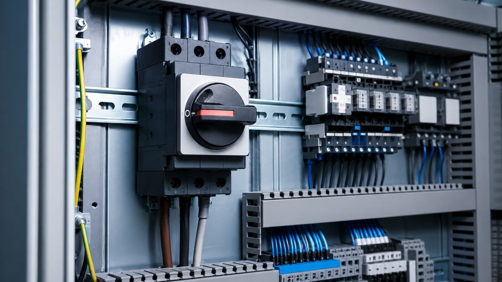
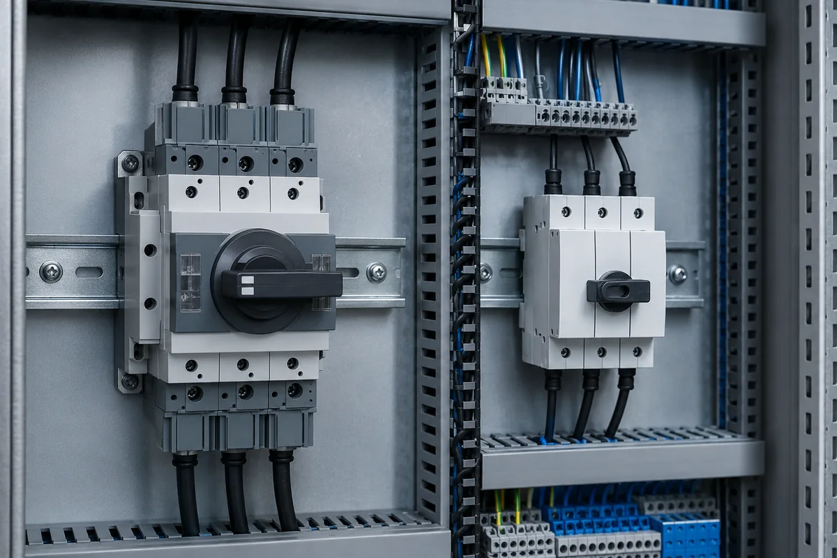
Confusion usually starts at the door handle. A rotary handle can operate a main switch, a switch-disconnector, a circuit breaker mechanism or an isolator mounted behind the panel. From outside the cabinet these can look similar, but they do not necessarily have the same electrical duty.
Labels can also be too short. “Isolator”, “main switch”, “disconnect switch” and “main disconnect” are sometimes used loosely in maintenance language. In design language, the exact device type, current rating, voltage rating, poles, utilisation category and manufacturer instructions matter.
Fuse switches add another layer. Some fuse-switch disconnectors are suitable for load switching. Some fuse carriers or fuse bases are not intended to be opened under load. The safe action depends on the device construction and rating, not only on the presence of fuses.
How to Read the Device Before Trusting It
| Marking or document item | Why it matters | Practical reading |
|---|---|---|
| Standard reference | Switches, disconnectors and switch-disconnectors are commonly selected under IEC/EN 60947-3. | Use the standard context to separate isolation duty from switching duty. |
| Rated operational current | The current rating is tied to voltage and load category. | A current value alone is incomplete unless the duty category is also suitable. |
| Utilisation category | Load types create different switching stress. | AC-21, AC-22 and AC-23 are not interchangeable for real loads. |
| Number of poles | The device may open phases only, or phases plus neutral where required. | Do not assume neutral is isolated unless the device and wiring prove it. |
| Short-time withstand | An isolating device may withstand fault current for a limited time without being the fault-breaking device. | Withstand capability is not the same as breaking short-circuit current. |
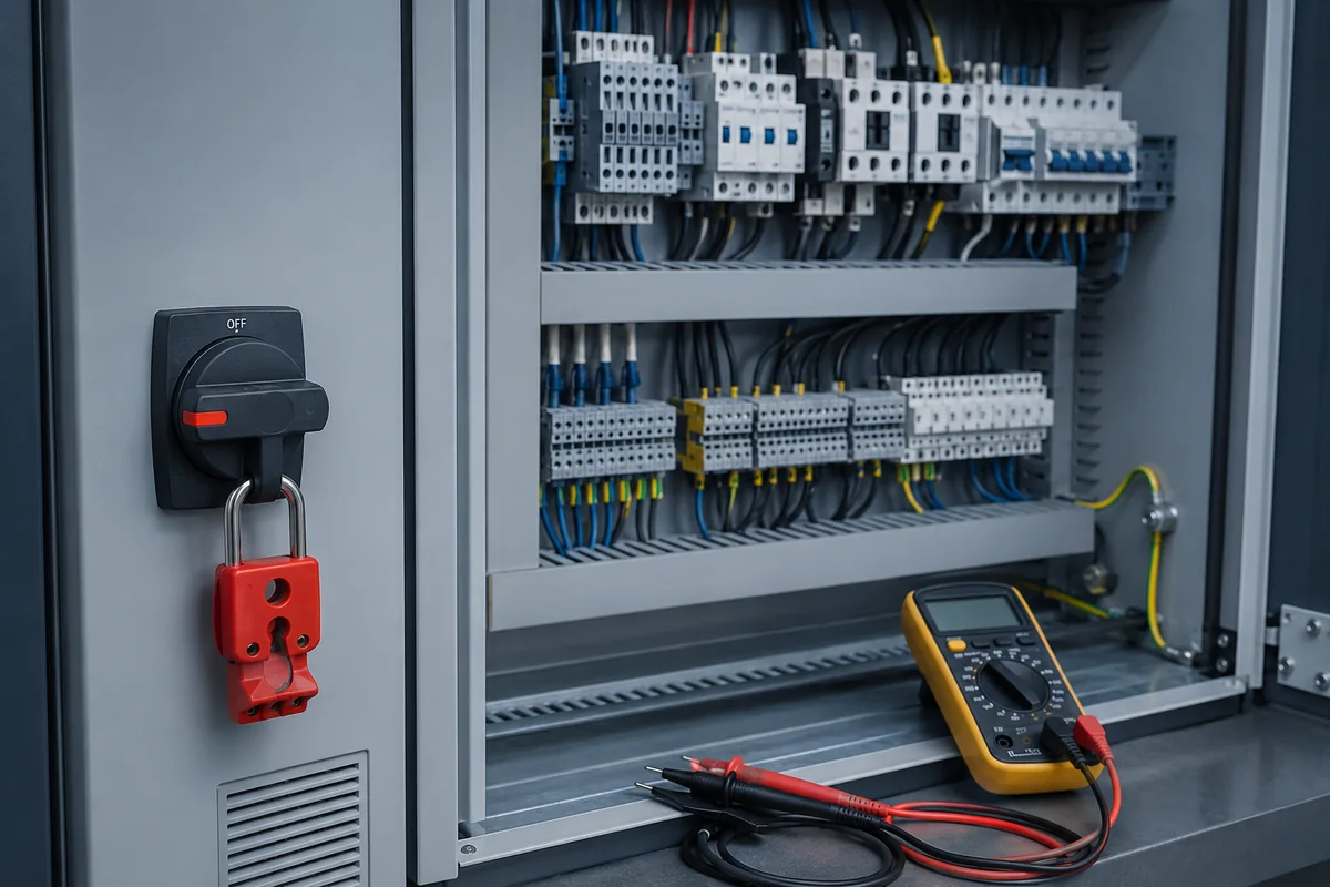
| Locking and indication | Maintenance isolation needs a dependable open position and a way to prevent re-closing. | Use lockable OFF and verified absence of voltage before work. |
Selection Matrix for Cabinet Isolation
| Cabinet location | Typical mistake | Better selection logic |
|---|---|---|
| Incoming main device | Choosing by enclosure handle size and nominal current only. | Select a switch-disconnector or suitable breaker according to load current, voltage, poles, fault context and lockout need. |
| Motor feeder service point | Using a device rated for a mild load where the circuit can interrupt motor current. | Check motor-duty utilisation category and whether switching under load is part of the intended operation. |
| Transformer primary | Treating transformer inrush as a simple resistive load. | Allow for magnetising inrush and the switching duty required by the design. |
| VFD or servo supply | Assuming OFF immediately makes the downstream equipment safe. | Consider DC bus discharge time, auxiliary feeds and manufacturer isolation instructions. |
| UPS-backed control circuit | Opening only the normal incoming supply and missing the backup source. | Identify all sources that can keep the control circuit live after the main handle is off. |
| Fuse holder or fuse base | Pulling fuses as if every fuse device were load-break rated. | Confirm whether the device is a load-break fuse-switch disconnector or an isolation-only fuse carrier. |
Load Type Matters: AC-21, AC-22 and AC-23
A device that can switch one kind of load may be unsuitable for another at the same current rating. Resistive loads, mixed loads and motor or highly inductive loads stress the contacts differently. This is why utilisation categories are part of the selection, not small print.
For a control panel, the practical question is simple: could this device be opened while the connected load is still drawing current, and what kind of current is that? A heater bank, a transformer primary and a motor feeder are not equal switching duties.
If the intended operation includes stopping or disconnecting a motor load, the motor-duty rating matters. If the device is only there to isolate after another switching device has removed the load, the requirements are different but still must be documented.
Safe Operating Logic Before Isolation Work
| Step | Purpose | What it prevents |
|---|---|---|
| Identify the device | Confirm whether it is load-break, isolation-only, switch-disconnector or protective device. | Using a similar-looking handle for a duty it is not rated to perform. |
| Understand the connected load | Check whether the circuit feeds motors, drives, transformers, heaters, control power or mixed loads. | Applying a mild-duty rating to a severe switching application. |
| Remove load where required | Stop the process or open the proper switching device before using an isolation-only device. | Arcing and damage caused by opening an unrated device under current. |
| Open and secure | Place the isolating device in the open position and lock it where the procedure requires lockout. | Unexpected re-energisation during maintenance. |
| Verify absence of voltage | Test at the correct terminals and consider auxiliary or backup sources. | Assuming the cabinet is dead because the main handle is off. |
| Wait for stored energy | Allow discharge time for drives, power supplies and capacitors. | Contact with a circuit that remains hazardous after the supply is opened. |
In practical work, the safest sequence is simple. Use the correct switching device for the intended duty, stop the load where required, isolate, secure the open position and then test at the right terminals. That last step matters because a door handle only proves the position of the operator mechanism, not the condition of every downstream circuit.
This is especially important where control transformers, UPS-backed circuits, drive DC buses or interlocked external equipment can keep part of the panel energised after the main device is open. The visual routine should always end with an electrical check.
Common Design and Maintenance Mistakes
When a Non-Load-Break Device Is Still Correct
A non-load-break isolating device is not automatically poor design. It can be correct when another device removes the current first and the isolator is used only to create a secure open point for inspection or maintenance.
This is common in assemblies where switching and isolation are intentionally separated. The problem begins when maintenance practice turns the isolator into the everyday switch, or when the drawing does not make the operating sequence clear.
Good design makes the sequence obvious: which device stops the load, which device isolates, which sources remain present and where absence of voltage must be verified.
Related Reading
Common Questions
What is the difference between a load-break and non-load-break switch?
A load-break switch is rated to make and break normal load current within its stated category. A non-load-break device is used for isolation after the load current has already been removed.
Can an isolator be opened under load?
An isolator or disconnector should not be used as a load switch unless the manufacturer rating clearly permits that duty. Opening an unrated device under load can produce arcing and contact damage.
Is a switch-disconnector the same as a load-break switch?
A switch-disconnector combines switching duty and isolating function when it is correctly rated. The exact duty still depends on the marked current, voltage and utilisation category.
Does a circuit breaker replace a load-break switch?
Not automatically. A circuit breaker provides protection and may also be suitable for isolation depending on its rating and application, but selection must follow the device standard, panel design and required duty.
Why do utilisation categories such as AC-21 and AC-23 matter?
They describe the type of load the device is rated to switch. A device suitable for resistive loads may not be suitable for motor or highly inductive loads at the same current.
What should be checked before opening a cabinet isolating device?
Check that the device is rated for the intended operation, stop or remove the load where required, follow the lockout procedure and verify absence of voltage at the correct terminals before work starts.