Main Switch vs Isolator in Control Cabinets
The Difference Is Not Just the Name
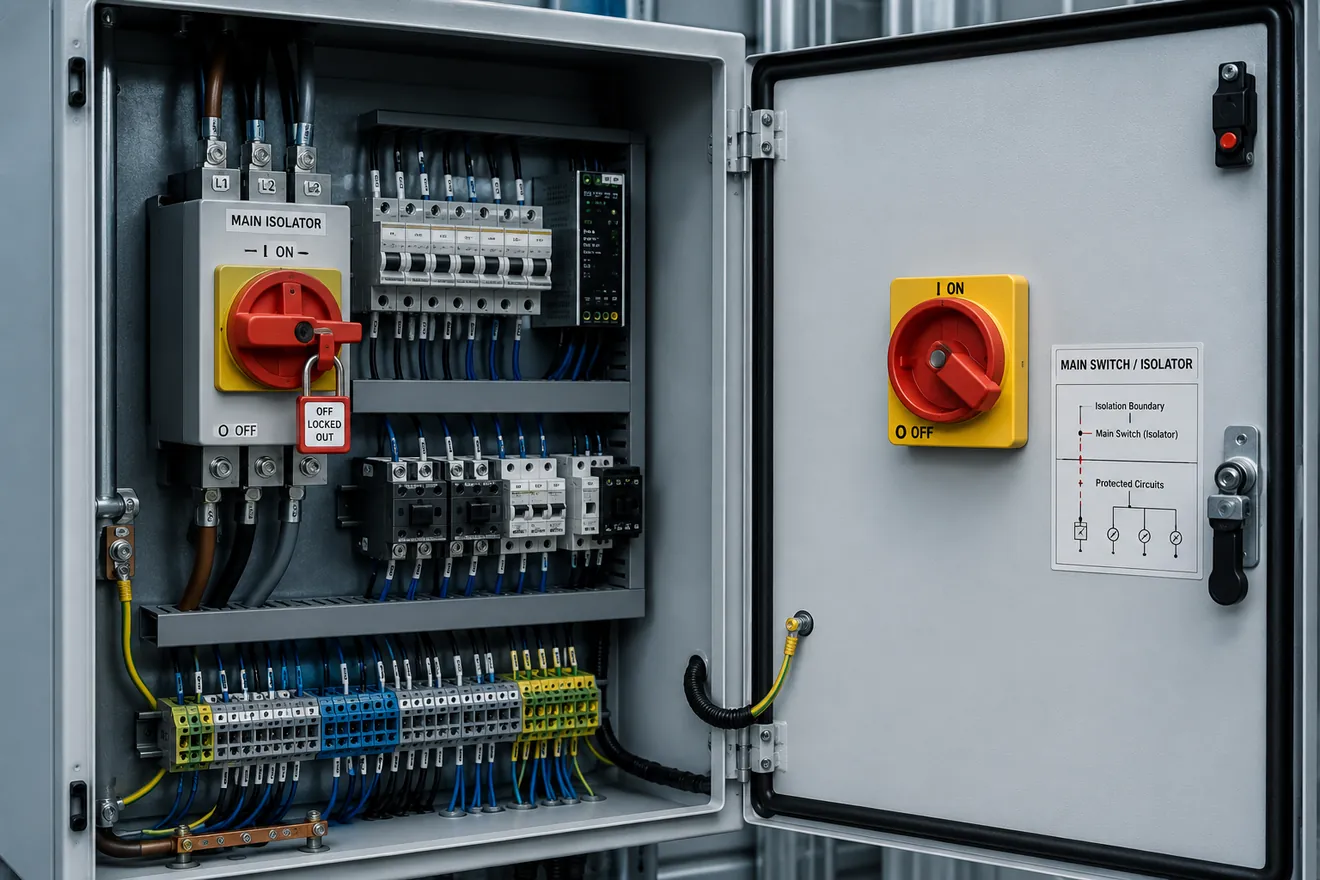
A main switch is normally the cabinet’s principal manual switching point. It may turn a machine section, distribution group or complete control panel on and off. An isolator is selected to create a defined separated state for work, inspection or maintenance.
In many industrial cabinets the same physical device may be a switch-disconnector, acting as both a main switch and an isolating point. That should be proven from the device marking, rating, wiring and drawings, not assumed from the handle colour or label.
The practical mistake is to treat every OFF handle as the same thing. One device may be intended for normal load switching. Another may be intended only to provide separation after the load has already been removed. A third may combine load switching and isolation when correctly selected.
Main Switch, Isolator and Switch-Disconnector Matrix
| Device function | Main role in a cabinet | What must be verified | Common misunderstanding |
|---|---|---|---|
| Main switch | Primary manual on/off point for a cabinet, machine section or supply path. | Rated current, voltage, utilisation category, load-switching duty and downstream boundary. | Assuming it makes every terminal inside the cabinet dead. |
| Isolator | Creates a clear separation point for work or inspection. | Open contact separation, visible/off indication, lockable position and all remaining live circuits. | Assuming it can break any load current safely. |
| Load-break switch | Switches normal load current under defined conditions. | AC/DC rating, load type, utilisation category and number of poles switched. | Assuming it provides the required isolation function by default. |
| Switch-disconnector | Combines switching capability with an isolating function when correctly selected. | Markings, contact separation, switching capacity, padlock provision and installation wiring. | Using the name without checking the actual product rating. |
| Circuit breaker used as a main disconnect | May provide switching and automatic fault protection, depending on device and mechanism. | Interrupting rating, isolation suitability, operating handle, trip indication and lock-off method. | Confusing fault protection with a verified isolation boundary. |
What Can Remain Live After the Main Switch Is Off
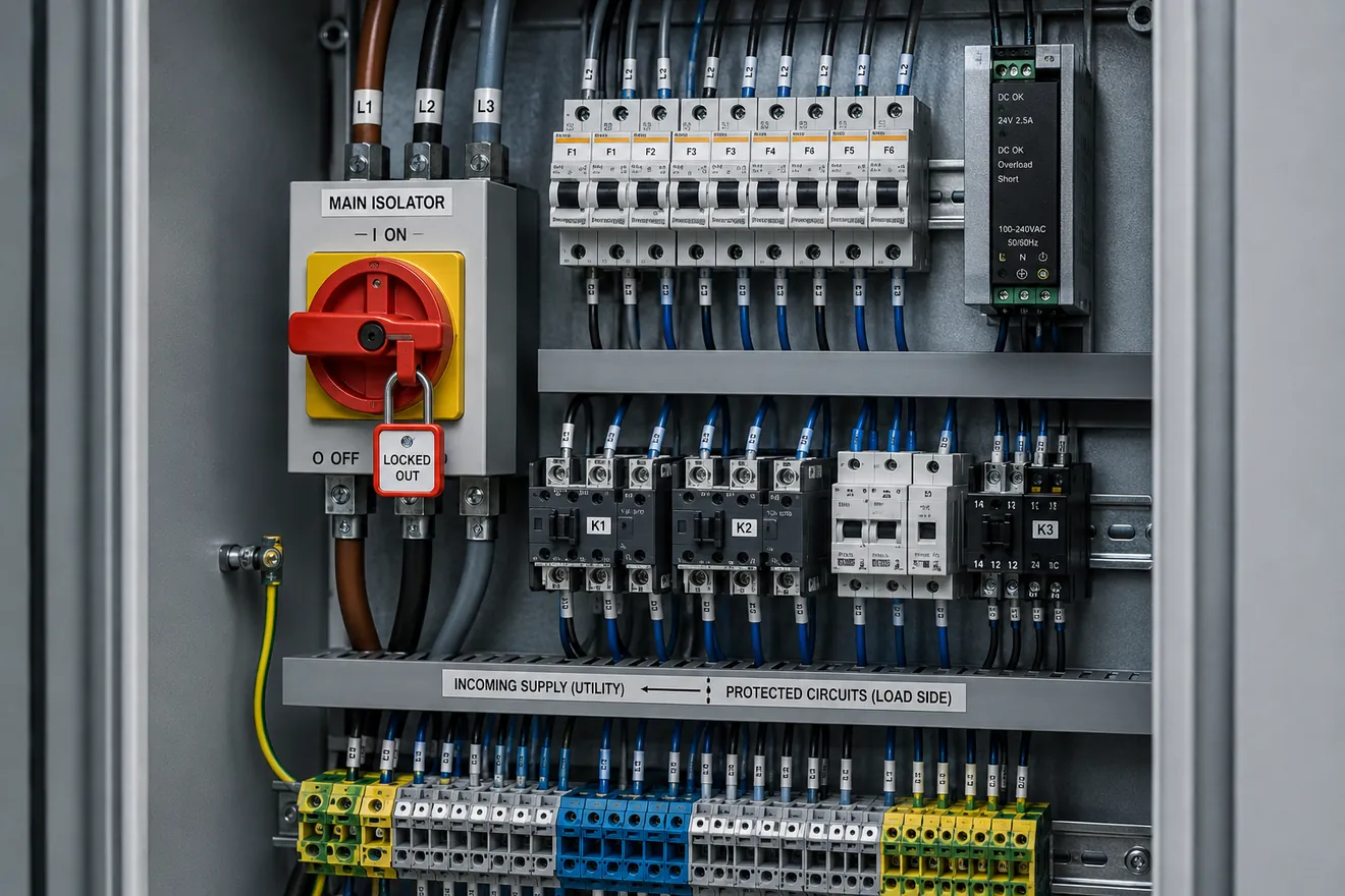
A cabinet can be off for its main power path and still contain live conductors. Common examples include panel lighting, service sockets, UPS-backed control power, remote inter-panel signals, monitoring circuits, external permissive contacts, heater feeds and terminals supplied from another enclosure.
This is why the isolation boundary must be found before work starts. The cabinet drawing should show the source and the switched side, but the actual panel should still be checked because modifications, retrofits and field wiring can change the practical risk.
Door interlocks and external handles support safe access, but they do not replace verification. They do not identify every backfeed, stored-energy source or terminal supplied from outside the cabinet.
Site Check Sequence Before Relying on OFF
| Step | What to inspect | Why it matters |
|---|---|---|
| 1. Identify the supply path | Incoming terminals, upstream feeder, transformer, DC supply and any external source. | The handle may not control every energy path entering the cabinet. |
| 2. Confirm the device function | Main switch, isolator, switch-disconnector, load-break switch or breaker mechanism. | The device name determines what ratings must be checked. |
| 3. Check load-switching duty | Current, voltage, AC/DC duty, load type and utilisation category. | Isolation and load breaking are related but not identical duties. |
| 4. Check lockable off-state | Padlock point, handle position, door interlock and possibility of defeat or bypass. | Maintenance depends on preventing unexpected re-energisation. |
| 5. Check remaining live circuits | UPS, sockets, lighting, heaters, external terminals, communication and signal wiring. | A cabinet may still contain live parts after the main load path is disconnected. |
| 6. Prove the work point | Test at the actual terminals or device being touched, not only at the handle. | The safe boundary is proven at the work location, not at the label. |
Door Interlocks and External Handles
In control cabinets, the external operating handle is often connected to a switch or breaker inside the enclosure. A door interlock may prevent the door from opening unless the disconnecting device is open, or it may require a key or tool depending on the cabinet arrangement.
The important point is not the presence of a handle alone. The safe arrangement depends on whether live parts remain accessible, whether the interlock can be bypassed, and whether any remaining energised circuits are protected and clearly identified.
Lockout, Labels and Drawings
A lockable OFF position supports lockout practice only when it controls the energy source relevant to the work. Labels should name the controlled section, not simply say “main switch” when external or auxiliary feeds remain live.
Drawings should match the installed cabinet. If the drawing shows no UPS or external feed but the cabinet has one, the isolation decision should follow the measured circuit, not the old document.
Common Faults and Misread Signals
| Observed condition | Possible meaning | Better check |
|---|---|---|
| Main handle off, pilot light still on | Separate control supply, UPS feed or panel light circuit. | Trace the light supply before assuming the cabinet is isolated. |
| Door opens only with handle off | Interlock is controlling access, not proving every conductor is dead. | Check all remaining live terminals and external sources. |
| Isolator hot or discoloured | Loose terminal, poor contact pressure or overload through the device. | Inspect terminals, conductor size, current and manufacturer torque data. |
| Switch trips upstream when operated | Downstream fault, inrush or switching device not suitable for the load. | Check load type, utilisation category and downstream insulation condition. |
| Technician cannot lock OFF | Wrong handle mechanism, missing lock provision or damaged actuator. | Do not treat it as a maintenance isolation point until corrected. |
Selection Sequence
Start with the work that must be made safe. Define the energy source, switched conductors, load type, available current, required isolation boundary, access method, lock-off requirement and remaining live circuits. Then select or verify the device: main switch, isolator, switch-disconnector, load-break switch or breaker mechanism. The correct answer is the device that matches the duty and proves a safe boundary at the actual work point.
Common Questions
Is a main switch the same as an isolator?
Not automatically. A main switch may also be a switch-disconnector, but the label alone does not prove the isolation boundary, load-switching duty or what remains live inside the cabinet.
Can an isolator switch load current?
Only if the selected device is rated for that duty. A device used only as an isolator may provide separation for work, while a load-break switch or switch-disconnector is selected for defined switching under load.
What should be checked before relying on the OFF position?
Check the wiring boundary, incoming and outgoing terminals, auxiliary feeds, UPS or external supplies, door interlock, padlockable handle, device markings and the actual absence of voltage at the work point.
Why can a cabinet still have live parts after the main switch is off?
Panel lights, socket outlets, UPS feeds, monitoring circuits, inter-panel signals or externally supplied terminals can remain energised if they are not downstream of the same disconnecting device.
Does a door interlock make a cabinet safe by itself?
No. A door interlock can support safe access, but it does not identify every remaining live circuit, stored energy source, backfeed or external terminal.
What is the practical difference between an isolator and a circuit breaker?
An isolator creates a manual separation point for work. A circuit breaker provides automatic overcurrent protection. Some devices combine functions, but each function must be verified from markings, ratings and drawings.