24 V DC Power Supply in Control Cabinets
What the 24 V DC Rail Supplies
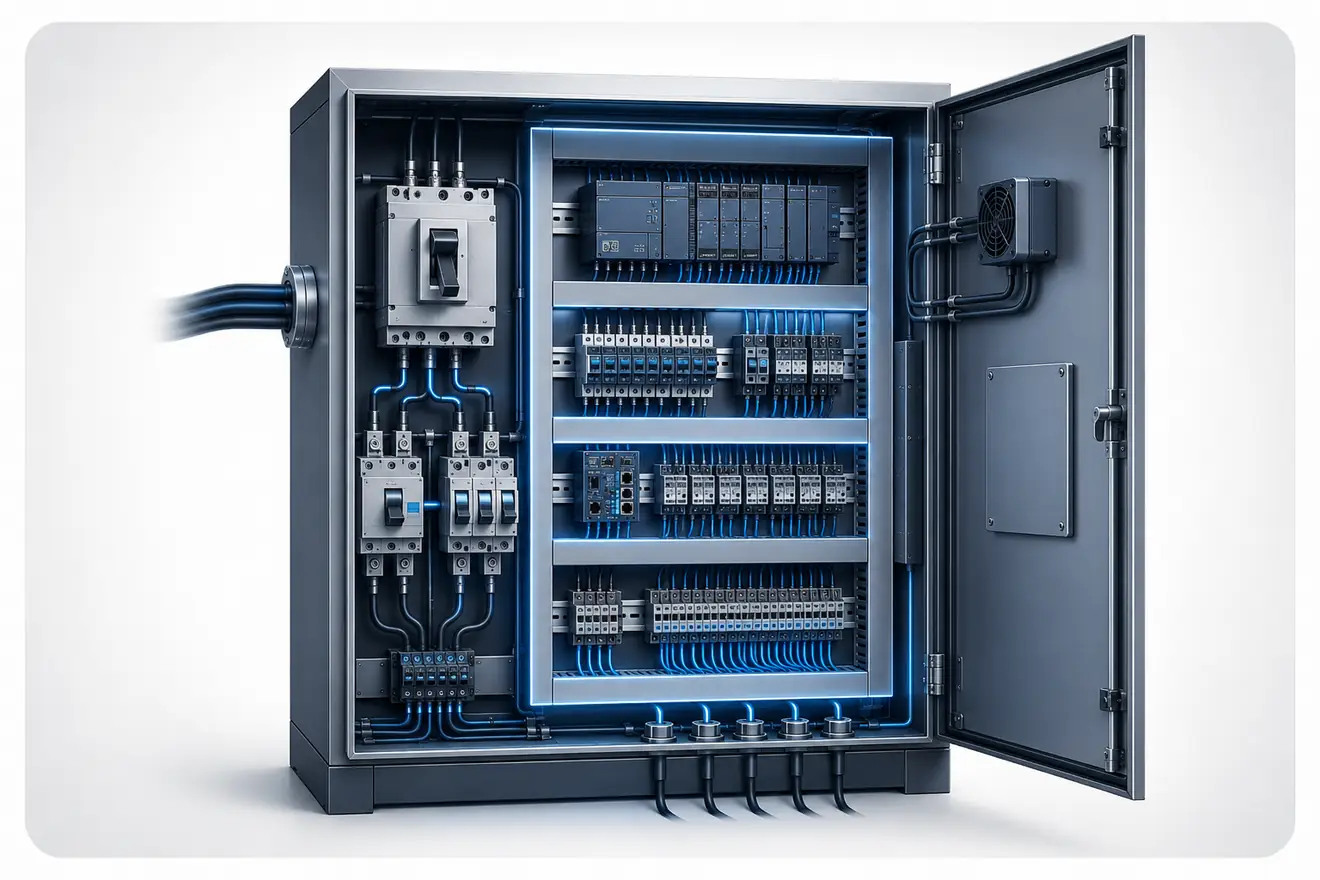
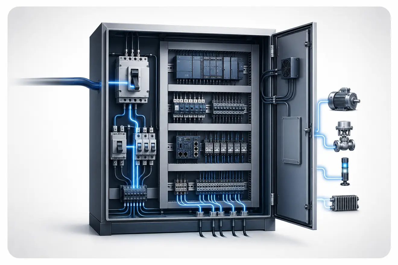
The 24 V rail commonly feeds PLC inputs and outputs, sensors, relays, contactor coils, indicators, interface modules, Ethernet switches and other low-voltage control devices. When this rail becomes unstable, the cabinet may still appear powered while the control system behaves erratically.
Supply capacity should be checked against measured current, not only against nameplate assumptions. Coil inrush, capacitive loads, lamps, network devices and modules starting at the same time can briefly demand more current than the steady-state load suggests.
Cabinet temperature also matters. A DIN rail power supply that is adequate in open air can lose usable margin inside a warm enclosure with dense wiring, nearby heat sources or restricted airflow.
The rail should also be viewed as a shared electrical reference. A fault on one branch can disturb other devices if branch protection, terminal layout or distribution grouping is weak.
Before replacing the supply
A replacement supply should only be considered after the rail has been measured under load. The same symptoms can come from branch wiring, terminal resistance, weak distribution, inrush current or thermal derating.
| Check | Reason |
|---|---|
| Load current | The operating load must remain below the usable output at cabinet temperature. |
| Inrush current | Coils, lamps and electronic modules can draw short peaks during energisation. |
| Voltage at load | The farthest device may receive less voltage than the supply terminals show. |
| Branch protection | Fuses, electronic protection and terminal blocks can create local symptoms. |
| DC OK contact | The alarm contact can indicate low output before the cabinet fully stops. |
Why the Supply Is Not Always the Fault
A 24 V DC power supply is only one part of the control-voltage path. A low-voltage complaint may start at the supply, but the same symptom can be created by loose terminals, undersized conductors, weak branch protection, a short-duration overload, enclosure heat or a load that draws more current than expected.
The useful test is not only the voltage seen on the supply terminals. The important question is whether enough voltage reaches the device at the moment it has to operate. A supply can hold a clean 24 V output while a remote sensor, relay coil, solenoid valve or I/O module sees a short dip during start-up, switching or simultaneous energisation.
For that reason, diagnosis should follow the path: supply output, branch protection, distribution terminals, field wiring and the actual load. A drop that appears after one fuse, electronic protection channel or terminal group points to the downstream circuit, not automatically to the supply itself.
Repeated PLC resets, contactor chatter, dim indicators, unstable analogue readings and intermittent sensor faults can be evidence of a power-path problem. Replacing the supply without checking voltage at the load can hide the real cause and leave the cabinet with the same fault pattern under the next high-demand cycle.
Load, Cable and Thermal Margin
A 24 V DC supply must be assessed as part of an electrical path. The available voltage at a device depends on supply regulation, load current, conductor resistance, branch protection, terminal pressure and the temperature inside the enclosure.
The basic relationship is direct: higher current through a longer or smaller conductor creates more voltage drop. The effect may be small at steady load and serious during inrush, switching or simultaneous energisation of several devices.
Sizing Logic for a 24 V DC Supply
| Factor | How it affects sizing | Practical result |
|---|---|---|
| Steady load | The total continuous current of PLC, sensors, relays, HMI, network and interface devices. | Sets the minimum current rating before any margin is added. |
| Simultaneous loads | Several outputs, coils or modules may energise at the same time. | The supply must handle real operating combinations, not only individual device ratings. |
| Inrush current | Capacitors, coils and lamps may draw short current peaks. | Short dips can cause resets even when the steady load looks acceptable. |
| Derating | High cabinet temperature reduces usable output current. | The selected supply must have margin at the expected enclosure temperature. |
| Voltage drop | Conductors, terminals and protection devices reduce voltage along the path. | The load-end voltage must remain inside the operating range of the device. |
Example Load Budget for a 24 V DC Cabinet Rail
| Load group | Current evidence | Why it matters |
|---|---|---|
| PLC CPU and I/O rack | Base current plus the current drawn by digital and analogue modules. | The control platform is usually a permanent load and should not be estimated from the CPU alone. |
| HMI and network switch | Continuous electronic load, often with a short start-up peak. | These devices can reset before the main control circuit appears fully failed. |
| Sensors and field devices | Sum by branch, with allowance for devices energised at the same time. | A large number of small loads can become significant on long field circuits. |
| Relay and contactor coils | Steady holding current plus pull-in current during energisation. | Coils create brief demand peaks and voltage dips during switching sequences. |
| Solenoid valves and lamps | Measured current during the real operating state, not only catalogue values. | These loads often explain dips that appear only during machine movement or alarm signalling. |
| Spare and service allowance | Documented spare capacity for later devices, not an unlimited reserve. | Enough margin helps reliability, but excessive oversizing can hide poor branch design. |
Typical Supply Sizes and Cabinet Use Cases
| Supply size | Common cabinet use | Risk if selected blindly |
|---|---|---|
| 2.5 A | Small control box, few sensors, simple relay logic or a compact PLC with limited field load. | Little spare margin for coils, lamps, network devices or later branch additions. |
| 5 A | Small to medium control cabinet with PLC, HMI, sensors and light interface load. | Can be marginal when several outputs energise together or when enclosure temperature is high. |
| 10 A | Medium cabinet with distributed I/O, solenoids, relays, network devices and separated branches. | May mask poor branch grouping if all loads are placed on one weak distribution path. |
| 20 A | Larger machine cabinet, multiple field branches, higher coil count or backed-up control sections. | Requires disciplined branch protection because fault current capability becomes more significant. |
Voltage Drop and Inrush Behaviour
Voltage drop in a DC control circuit is not only a design calculation. It is also a diagnostic measurement. The same supply can look healthy at its terminals and still deliver marginal voltage to a remote device through a long route, small conductor, warm terminal or overloaded branch.
Inrush current is another common reason for short instability. A group of coils, lamps, electronic modules or capacitive inputs can pull a high peak during energisation. The voltage rail may recover quickly, but the control system can still record a reset, communication fault or input error.
Ripple, Noise and Sensitive I/O
A 24 V DC rail can be within its average voltage range and still disturb sensitive equipment. Excessive ripple, switching noise, poor common reference, mixed routing with noisy loads or weak segregation between solenoid branches and analogue circuits can appear as unstable input readings, communication errors or drifting analogue values.
Analogue input modules, weighing electronics, encoders, pressure transmitters and communication devices should not be judged only by a steady multimeter reading. Where symptoms are intermittent, compare the rail during switching events and separate noisy loads from the branch that feeds sensitive electronics.
Fault Patterns on a 24 V Rail
Diagnostic Sequence
| Step | What to prove | What the result means |
|---|---|---|
| Input side | Correct AC or DC input voltage at the supply terminals. | No stable input means the problem is upstream of the power supply. |
| Output side | Stable DC voltage at the supply output under load. | Low output can indicate overload, derating, heat or supply failure. |
| Distribution | Voltage after branch protection and terminal blocks. | A local drop points to protection, terminals, wiring or branch load. |
| Load end | Voltage at the device during the fault condition. | The device end confirms whether the load receives usable voltage. |
| Timing | When the drop appears: start-up, switching, warm operation or random events. | Fault timing separates inrush, heat, intermittent terminals and overload. |
DC OK, Backup and Cabinet Heat
The DC OK contact is useful, but it is not a complete diagnosis. It normally reports whether the supply output is inside a defined range. It does not prove that every branch receives proper voltage, and it does not identify a weak terminal, undersized conductor or overloaded device.
Buffer modules, redundancy modules and DIN rail UPS units add another layer to the power path. They can keep the rail alive during short interruptions, but they still require correct sizing, battery condition checks, branch separation and clear knowledge of which loads are backed up.
Heat remains one of the most common hidden limits. A supply mounted near warm drives, dense wiring ducts or other heat sources may require derating even when the calculated current appears acceptable.
| Element | What it can confirm | What it cannot prove alone |
|---|---|---|
| DC OK contact | Supply output is inside the manufacturer-defined operating range. | Voltage quality at the far load or condition of every branch. |
| Buffer module | Short interruption support for selected loads. | Correct load priority, battery health or wiring condition. |
| Redundancy module | Separation between parallel supplies or supply paths. | Whether both supplies are equally loaded or thermally healthy. |
| DIN rail UPS | Backup operation during input loss. | Whether all connected loads should remain powered during shutdown. |
Fault Evidence Table
| Symptom | Likely power-path cause | Useful check |
|---|---|---|
| PLC reset during start-up | Inrush peak or insufficient supply margin. | Measure rail voltage during start-up with normal loads connected. |
| Contactor chatter | Low coil voltage or voltage dip during switching. | Measure at the coil terminals during energisation. |
| Sensor faults on one branch | Branch protection, terminal condition or local cable drop. | Compare voltage at the supply, branch output and sensor connector. |
| Faults after warm-up | Power supply derating, cabinet heat or terminal expansion. | Measure load current and cabinet temperature after stable operation. |
| DC OK alarm without shutdown | Output briefly leaves the allowed range. | Check event timing and loads that switch at the same moment. |
Related Reading
Common Questions
What does a 24 V DC power supply feed in a control cabinet?
It commonly feeds PLC modules, sensors, relays, contactor coils, indicators, interface modules, network devices and other low-voltage control circuits.
How should a 24 V DC power supply be sized?
Start with steady load current, then allow for inrush current, simultaneity, cabinet temperature, derating, voltage drop and operating margin.
Is a larger 24 V DC supply always safer?
No. Extra capacity can be useful, but a much larger supply still needs correct branch protection, conductor sizing, terminal quality and load grouping so faults remain controlled.
Why should voltage be measured at the load?
The load can receive lower voltage than the supply terminals show because of conductor resistance, terminal condition, branch protection, current demand and cable length.
What does a DC OK contact prove?
It usually proves that the supply output remains within a defined range, but it does not prove correct voltage at every branch and load.
Can cabinet heat reduce usable power supply output?
Yes. Higher enclosure temperature and poor airflow reduce usable output margin and can force derating even when the nominal current appears sufficient.