Isolation boundary

What Remains Live After the Main Disconnect Is Switched Off?

Switching the main disconnect OFF normally removes power from its load side. It does not automatically de-energise incoming line-side terminals, circuits supplied from another source, UPS-backed circuits, backfeed paths or voltage stored in capacitors and drive DC buses.
Main disconnect
Line side
External sources
Stored energy
Verification
Normal result
Load-side bus isolated
Critical check
Other sources still present?
Direct answerThe OFF position shows only that the disconnect is open. It does not prove that every conductor in the enclosure is at zero volts. Drawings, source labels and an approved absence-of-voltage test are needed to establish the actual electrical state.
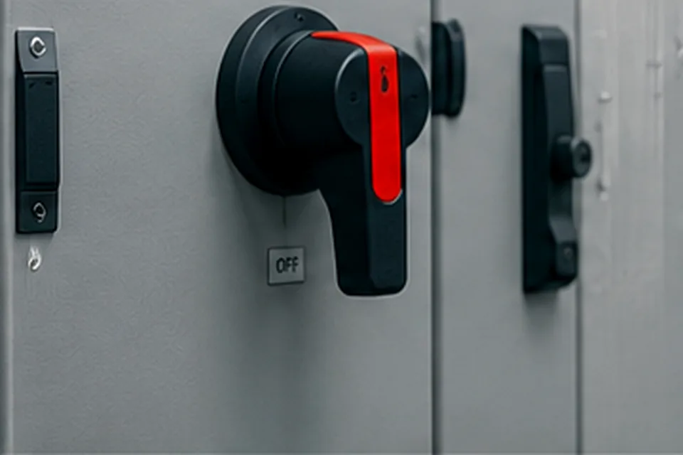
General view of an industrial control cabinet with a main disconnect handle
General view of an industrial control cabinet. Use the drawings and source labels to identify every supply, then verify the conductors before work.

The Answer in One Minute

A main disconnect opens the current path through its own poles. The conductors and devices connected downstream of those poles are normally de-energised, provided that no alternative supply or backfeed path reaches them.

The supply side is different. Incoming terminals and any taps taken before the disconnect can remain energised until an upstream isolating device opens. A panel may also contain external control voltage, UPS or battery circuits, remote I/O power, service circuits or a second source that the main handle does not control.

Drives and power supplies introduce another category: stored energy. Their supply may be removed while internal capacitors still hold voltage temporarily. That is different from a circuit that is still being supplied, but it still means zero volts cannot be assumed.

State summary

What OFF can and cannot prove

ObservationWhat it proves
Main handle is OFFThe disconnect mechanism is in its open position.
Load-side bus loses powerThe normal downstream supply path has opened.
Incoming terminals remain connected upstreamThe line side can still be energised.
External or stored sources existOther points can remain live despite the main handle position.

The Boundary of the Main Disconnect

Treat the main disconnect as the dividing point between the incoming supply and the circuits it normally controls.

The line-side terminals remain connected to the upstream feeder. If the enclosure contains a control transformer primary, lighting circuit, service socket or monitoring device tapped before the disconnect, that equipment belongs to the supply side as well.

The load side is normally de-energised when the device opens, but not if a second supply, backfeed path or cross-cabinet connection can feed the same bus or connected circuit.

Design question
Do not ask only, “Is the switch OFF?” Ask, “Which conductors pass through this device, and which conductors reach the cabinet by another path?”
Isolation boundary in words

Read the normal feeder from source to load. The open main disconnect interrupts only the conductors routed through its own poles.

  1. Still suppliedUpstream feeder

    The utility, transformer or upstream distribution device remains the source until it is isolated elsewhere.

  2. Line sideIncoming terminals and conductors

    These are connected before the main disconnect and can remain energised while the upstream feeder is live.

  3. Boundary deviceMain disconnect — open / OFF

    The device creates an open gap only across the poles included in that disconnect.

  4. Normally isolatedLoad-side bus

    This bus normally loses its feeder when the disconnect opens, provided no alternate source or backfeed exists.

  5. Verify separatelyLoad-side equipment

    Normal supply may be removed, but external feeds and stored energy can still leave specific points energised.

Bypass path 1

Line-side auxiliary tap or control transformer

A primary connection taken before the main poles remains on the line side. Its secondary control circuit can therefore remain energised after the main handle is OFF.

Bypass path 2

External 24 V DC or another separate source

The +24 V and 0 V conductors enter independently and do not pass through the three-phase disconnect. The supplied PLC, I/O or interface can stay powered.

Boundary rule: the main disconnect isolates only the conductors routed through its poles. Anything upstream, connected around the poles or supplied from another source remains a separate energy path.

What Can Remain Live After the Main Disconnect Is OFF?

The table separates continuously supplied sources from stored energy and from circuits that are normally isolated.
Part or circuitPossible stateWhy
Incoming line-side terminals and cablesCan remain liveThey are upstream of the disconnect poles.
Line-side tap, control-transformer primary and its supplied secondary circuitCan remain liveThe primary connection is taken before the main disconnect, so the transformer secondary can also remain supplied.
External 24 V DC terminalsCan remain liveThe source is located in another panel, power supply or system.
UPS or battery-backed PLC circuitCan remain liveThe backup source continues to supply the circuit.
Cabinet light or service socketCan remain liveSome designs supply these circuits before the main disconnect or separately.
Remote I/O, powered signal interface or PoE connectionMay remain livePower or reference voltage can arrive through another system connection.
VFD or servo DC busTemporary voltageInternal capacitors can retain energy after the input supply is removed.
Main load-side busNormally offThe disconnect opens its normal supply path, assuming no alternate source exists.
A note on 24 V DC
A remaining 24 V DC circuit may present a different shock risk from the mains supply, but it can still cause unexpected operation, equipment damage, arcing or a hazardous release of energy.

Sources That Bypass the Main Disconnect

Many panels contain more than one electrical source even though the door has only one main-disconnect handle. The additional source may be intentional, such as an external control supply or UPS, or it may come from a connected machine section, regenerative drive, redundant supply or powered communication link.

Start by tracing every conductor that enters the enclosure and every connection that can feed energy back into it. The single-line diagram, terminal plan, warning labels and physical wiring should all agree.

External control voltage

24 V DC or another control voltage may arrive from a separate cabinet and stay present when the local main disconnect opens.

UPS and batteries

Backup power is designed to survive loss of the normal mains supply, so it requires its own isolation point and documentation.

Remote equipment

Inter-panel links, remote I/O and powered interfaces can introduce voltage from equipment that is still operating.

Backfeed paths

Regenerative or active-front-end drives, common DC-bus systems and other connected sources can feed energy back into a circuit that appears locally isolated.

Remaining source paths

For each path, identify its origin, the conductors that bring it into the cabinet and the device that isolates it.

Separate source

External control voltage

Origin
Another cabinet, remote power supply or field distribution unit.
Entry path
+24 V / 0 V, another control-voltage pair or shared reference conductors.
Why it remains
The conductors do not pass through the local main disconnect.
Isolation need
Identify and isolate the remote source, then verify the affected conductors.
Backup source

UPS or battery circuit

Origin
UPS output, battery pack or battery-backed power supply.
Entry path
Protected control, network, safety or monitoring circuits.
Why it remains
The backup source is designed to continue operating when normal AC power is lost.
Isolation need
Control both the normal input and the stored or backup source according to the equipment procedure.
Line-side connection

Auxiliary circuit or control transformer

Origin
Tap taken from incoming conductors before the main disconnect poles.
Entry path
Transformer primary, cabinet light, heater, service socket or auxiliary branch.
Why it remains
Opening the main poles does not interrupt the upstream tap.
Isolation need
Use the separately identified disconnecting means and verify both primary and supplied secondary circuits.
Remote interface

Powered communication or signal wiring

Origin
Remote I/O, PoE equipment, powered interface or another operating system.
Entry path
Communication cable, powered interface conductors or shared reference conductors.
Why it remains
The remote equipment remains energised and can introduce power or reference voltage.
Isolation need
Identify whether the interface is powered and isolate or disconnect it at the appropriate source.
Return path

Backfeed from connected equipment

Origin
Regenerative or active-front-end drive, common DC bus, generator, PV system or another panel.
Entry path
Power conductors or a shared DC link connected to the local circuit.
Why it remains
Energy can return towards a circuit that appears locally isolated.
Isolation need
Trace and control every connected source and verify for unrelated backfeed.
Excepted auxiliary load

Cabinet light or service socket

Origin
Line-side branch or separately supplied auxiliary circuit.
Entry path
Dedicated branch circuit entering the enclosure.
Why it remains
It may be intentionally available while the machine supply is disconnected.
Isolation need
Follow its separate label and disconnecting means; do not infer its state from the main handle.
Source check
Trace every cable entering the enclosure, every source connected to a common bus and every circuit tapped before the main poles. One main handle does not mean the cabinet has only one source.

Design Measures That Make the Isolation Boundary Clear

A clear design keeps incoming live parts separate, gives each source its own isolation point and makes every exception easy to identify.
Separate incoming live partsUse suitable barriers, shrouds or a separate disconnect enclosure so line-side parts are not confused with the isolated load-side area.
Give each source an isolation pointExternal control power, UPS outputs and other independent supplies need a defined means of isolation that appears on the drawing.
Group and identify terminalsKeep externally supplied and line-side terminals together where practical, with durable source identification that matches the terminal plan.
Control backfeed pathsUse suitable interlocking and switching, together with the manufacturer's specified arrangement, so one source cannot re-energise a circuit that is supposed to be isolated.
Show stored-energy devicesPlace discharge information and verification points where technicians can relate them to the actual drive, servo or power-supply circuit.
Keep revisions synchronisedField modifications must update the single-line diagram, terminal plan, labels and isolation schedule at the same time.

Supplied Voltage Is Not the Same as Stored Energy

A line-side terminal can remain energised continuously because an upstream source is still connected. A drive DC bus can remain at a hazardous voltage for a different reason: its capacitors were charged before the disconnect opened.

This distinction matters during troubleshooting and documentation. A continuously supplied source requires isolation of the source path. For stored energy, observe the manufacturer-specified discharge time, check any relevant status indicators, and then use the approved voltage-verification procedure.

Do not treat a dark display, stopped fan or elapsed rule-of-thumb delay as proof that stored voltage is gone. Use the equipment documentation for the required discharge time, then verify the voltage before work.

Stored-energy verification path

Opening the input path removes the source, but it does not prove that internal capacitors or a DC link have discharged.

Continuously supplied voltage

Remains present while an upstream, external or backfeeding source is connected. Waiting alone does not remove it.

Stored electrical energy

May decay after the source is removed, but the actual state depends on the equipment, discharge circuit and possible faults.

  1. 1
    Identify and isolate every source

    Include the normal feeder, separate control supplies, UPS or batteries, connected DC buses and possible backfeed paths.

  2. 2
    Apply the required lockout or equivalent control

    Use the site and equipment procedure for each identified source rather than relying on the local handle position.

  3. 3
    Observe the manufacturer-specified discharge time

    This gives the designed discharge circuit time to reduce stored voltage; it is not final proof by itself.

  4. 4
    Use indicators only as supporting information

    A dark display or extinguished charge lamp can support the assessment but must not be treated as proof of zero voltage.

  5. 5
    Prove the tester before measurement

    Confirm the approved instrument operates correctly on a known source as required by the applicable procedure.

  6. 6
    Verify designated points and re-prove the tester

    Check the relevant conductors and internal points, then confirm the instrument still operates correctly.

Final check: the discharge time is not proof of zero voltage. Verify the actual condition at the required test points.

Two Practical Cabinet Examples

Same OFF handle — two different electrical states

The handle is in the same position in both examples, but the electrical state is different because the supply paths are different.

Example 1 · one supply path

Single feeder with all normal branches on the load side

  1. Upstream feeder and line-side terminalsRemain energised until the upstream source is isolated.
  2. Main disconnectOpen; the normal feeder path is interrupted.
  3. Load-side bus and PLC power supplyNormally de-energised because they are supplied only through the open disconnect.
  4. VFD or power-supply DC linkInput power is removed, but internal capacitors may retain voltage temporarily.

Result: line side live, normal load-side supply off, stored energy checked separately.

Example 2 · two supply paths

Main feeder plus an external 24 V DC control supply

  1. Three-phase feeder and line-side terminalsRemain energised upstream of the open main disconnect.
  2. Three-phase load-side busNormally de-energised when the main poles open.
  3. External +24 V and 0 V pairEnters independently and is not interrupted by the three-phase disconnect.
  4. PLC, remote I/O or interfaceCan remain powered even though the main load bus is off.

Result: the panel is partly energised; the external control source requires its own isolation and verification.

The handle shows the position of one device. The drawings and source list show whether other energy paths remain.

Signs That a Panel Is Still Partly Energised

These signs do not identify the source by themselves, but they show where the drawing and isolation checks should begin.
PLC or HMI remains onLook for external 24 V DC, a UPS, battery support or a control supply that does not pass through the main disconnect.
Light or socket still worksCheck whether the service circuit is connected on the line side or treated as a separately supplied circuit.
Voltage falls graduallyA decaying reading points toward capacitors or a drive DC bus rather than a continuously connected source.
Voltage returns unexpectedlyInvestigate backfeed, regeneration, a redundant source, remote equipment or automatic source restoration.
Do not treat symptoms as proof
A symptom narrows the search; it does not establish a safe state. Use the current drawings, identify every source and apply the approved verification procedure.

Verification Sequence Before Work

This is a planning sequence for qualified personnel. It does not replace the site electrical-safety procedure, equipment instructions or local legal requirements.
StepEvidence to establishWhy it matters
1. Identify every sourceMain feeder, external control power, UPS, battery, remote connections and possible backfeed.A source that is not identified cannot be reliably isolated.
2. Read the drawings and labelsSingle-line diagram, terminal plan, source warnings and disconnect schedule.They define the intended isolation boundary and known exceptions.
3. Operate and secure each required isolating meansThe devices controlling all relevant sources, not only the local main handle.Separate sources require separate isolation actions.
4. Account for stored energyDrive, servo, power-supply and mechanical energy discharge requirements.Removed supply does not instantly remove every hazardous energy state.
5. Verify absence of voltageApproved test method at the required points within the work boundary.Verification establishes the actual electrical state; handle position does not.
6. Confirm the state remains controlledNo automatic restart, remote re-energisation or source restoration can occur.The safe state must remain valid for the duration of the work.
Safety boundary
This page is an engineering reference, not permission to open or test energised equipment. Follow the approved lockout, isolation and voltage-verification procedure for the installation.

Standards Context

Requirements vary with the equipment, jurisdiction and adopted edition. Across the main industrial-panel frameworks, the common principle is that a disconnect handle does not replace source identification, control of hazardous energy or voltage verification.
IEC 60204-1

Machine supply isolation

Covers the supply-disconnecting device, circuits that it does not disconnect, warning information and residual electrical energy.

NFPA 79

Excepted circuits

Recognises circuits that remain energised with the main disconnect open and separately addresses hazards associated with charged capacitors.

UL 508A

Panel identification

Addresses supply-side connections, multiple supply circuits, disconnect identification and associated panel markings.

OSHA / NFPA 70E

Safe work condition

Turning a device OFF is not the final proof. All relevant sources must be controlled and absence of voltage established by the applicable work procedure.

Technical basis

Relevant standards and guidance

This article draws on the following control-panel and electrical-safety references. Confirm the edition adopted for the project and jurisdiction before applying any requirement to an installation.

  • IEC 60204-1:2016+A1:2021 — Safety of machinery — Electrical equipment of machines — Part 1: General requirements.
  • NFPA 79 (2024 edition) — Electrical Standard for Industrial Machinery.
  • UL 508A, Third Edition — Standard for Industrial Control Panels.
  • NFPA 70E (2027 edition) — Standard for Electrical Safety in the Workplace.
  • OSHA 29 CFR 1910.333 — Selection and use of work practices.
  • Eaton — Control panel design guide according to UL 508A.
  • UL Solutions — Machine Supply Circuit and Disconnecting Means.
Use the applicable edition
This summary gives design context only. Project specifications, local law, the adopted code edition, equipment instructions and the employer's electrical-safety programme control the actual requirement.

Drawing and Marking Checks

Incoming side shown clearlyThe drawing distinguishes the line side from the bus and branch circuits controlled by the disconnect.
External sources identifiedEach independent supply has a source reference, isolation point and terminal designation.
Exceptions are visibleLighting, sockets, heaters or control transformers connected before the main disconnect are not hidden in general wiring.
Stored-energy devices notedDrive and servo discharge requirements are available where maintenance decisions are made.
Door warning matches realityThe warning reflects the actual number and type of sources, not a generic label applied to every cabinet.
Field wiring matches drawingsLater modifications and temporary feeds have not invalidated the documented isolation boundary.

Common Mistakes

MistakeWhy it failsBetter question
Assuming OFF means the whole enclosure is deadThe disconnect controls only the conductors routed through it.Which parts are on the line side or another source?
Checking only the main feederExternal control power, UPS and remote systems can stay energised.How many independent sources enter the cabinet?
Treating stored energy as ordinary supply voltageThe isolation and discharge mechanisms are different.Is the voltage continuously supplied or retained in capacitors?
Relying on indicator lamps or displaysAn indicator can fail, be wired elsewhere or turn off before voltage disappears.What approved verification establishes absence of voltage?
Ignoring later field modificationsAdded power supplies and cross-cabinet wiring can bypass the original disconnect design.Does the physical wiring still match the latest drawing?

Related Reading

This page covers the isolation boundary after the main disconnect is OFF. The related pages explain device terminology and load-breaking capability.

Common Questions

Does switching the main disconnect OFF make the whole panel dead?

No. It normally isolates the load side of the disconnect, but incoming line-side terminals, external supplies, UPS-backed circuits and stored energy can remain present.

Are the incoming terminals still live when the disconnect is OFF?

Usually yes, unless an upstream device has also isolated the supply. The incoming terminals are on the line side of the disconnect.

Can an external 24 V DC supply remain live?

Yes. A supply arriving from another cabinet, UPS, battery or remote power unit is not necessarily controlled by the panel main disconnect.

Is stored energy the same as an external live supply?

No. A continuously supplied circuit can remain energised indefinitely. Stored energy in capacitors or drive DC buses may decay, but it still requires verification before work.

Can a cabinet light or service socket remain powered?

Yes, if it is connected on the line side or supplied from a separate source. The wiring diagram and labels must show that exception.

Does the OFF handle prove absence of voltage?

No. The handle position shows only the mechanical state of the disconnect. Absence of voltage must be established using the approved isolation and verification procedure for the equipment.

Can powered communication or signal wiring bring voltage into a panel?

Yes. Remote I/O, PoE, powered interfaces and some signal circuits can introduce power or reference voltage from another system.

What is normally de-energised after the main disconnect opens?

The main load-side bus and circuits supplied only from that bus are normally de-energised, provided that no alternate source or backfeed path exists.