24 V DC MCBs and Electronic Circuit Protectors
The Weak Point Is the Fault Path
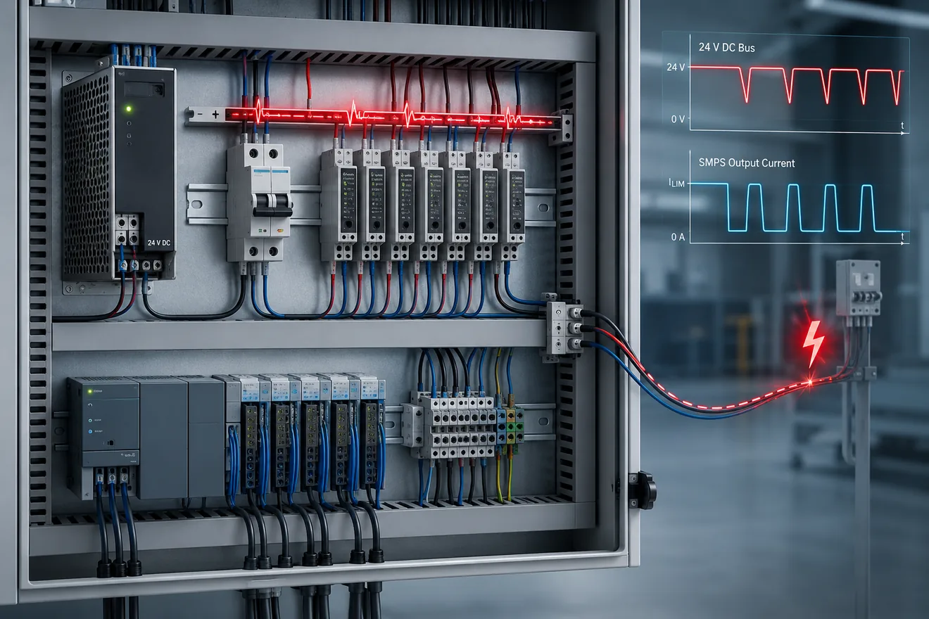
A conventional MCB is often selected by rated current and trip curve. That is not enough for 24 V DC branch protection. The device must see enough current during a downstream short circuit to operate before the shared power supply collapses.
On a compact cabinet backplate the short-circuit current may be high. At the end of a 40 m, 60 m or 100 m field cable, the outgoing and return conductors add resistance. The fault current can fall below the magnetic trip region of a C-curve MCB.
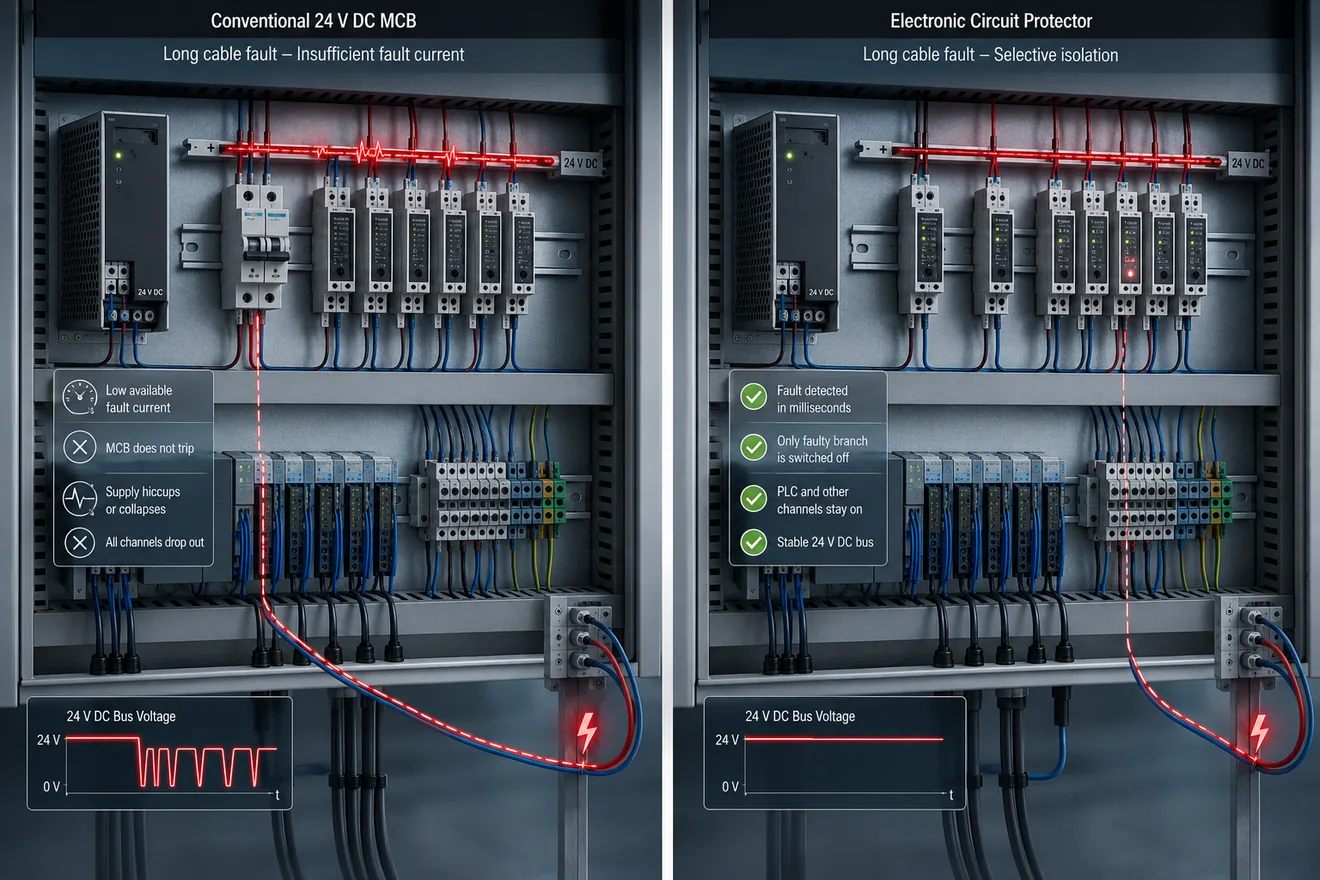
That is why a circuit can look correctly protected on paper, but still fail in operation: the breaker remains closed, the power supply enters current limit or hiccup mode, and every PLC, I/O module and sensor fed from the same rail sees the voltage drop.
Fault Current Calculation
Quick Fault Current Estimator
Use this rough check to see how cable length changes the available short-circuit current. It assumes 24 V DC, copper conductors, outgoing and return loop length, and 0.3 Ω allowance for source, terminals and contacts.
| Element | What it means | Why it matters |
|---|---|---|
| UDC | Available 24 V DC voltage under the fault condition. | Voltage may sag when the SMPS reaches current limit. |
| Rsource | Power supply output impedance, internal protection and distribution resistance. | The source is not an ideal battery. Its output mode controls the fault. |
| Rline | Outgoing and return conductor resistance to the field device. | Long cable runs usually dominate the calculation. |
| Rcontact | Terminals, plugs, relay contacts, sensor connectors and field junctions. | Small added resistances can decide whether the breaker trips or the rail collapses. |
Worked Example: Long Sensor Cable
Assume a 24 V DC branch feeds a remote sensor group through a 0.75 mm² copper pair. The short circuit happens at the far end of the cable. The loop length is twice the one-way distance because current must travel out and return.
Using 0.0175 Ω·mm²/m as a simple copper resistance value and allowing 0.3 Ω for source, contact and distribution resistance, the available fault current falls quickly as distance grows.
A 2 A C-curve MCB may need roughly 10 A to 20 A for magnetic operation. A 4 A C-curve MCB may need roughly 20 A to 40 A. If the end-of-line fault current is below that region, fast magnetic tripping should not be assumed.
Illustrative End-of-Line Fault Current
| One-way cable length | 0.75 mm² loop resistance | Approx. fault current | 1.5 mm² loop resistance | Approx. fault current | Protection reading |
|---|---|---|---|---|---|
| 10 m | 0.47 Ω | 31 A | 0.23 Ω | 45 A | Fast breaker operation may be possible, depending on curve and supply. |
| 25 m | 1.17 Ω | 16 A | 0.58 Ω | 27 A | Small C-curve devices become uncertain; larger ratings may not trip fast. |
| 50 m | 2.33 Ω | 9 A | 1.17 Ω | 16 A | Thermal-magnetic protection may be too slow for selective 24 V DC fault clearing. |
| 75 m | 3.50 Ω | 6 A | 1.75 Ω | 12 A | The SMPS is likely to influence the event before the MCB clears the branch. |
| 100 m | 4.67 Ω | 5 A | 2.33 Ω | 9 A | Electronic channel protection should be considered for dependable branch isolation. |
What Happens When the SMPS Reacts First
MCB, Fuse or Electronic Protector?
The question is not whether an MCB is “bad”. The question is whether it can isolate the specific 24 V DC branch under the worst realistic cable fault. Short cabinet wiring, high available current and simple loads may still suit conventional devices.
Electronic circuit protectors are stronger where the available current is limited, where channels must remain selective, or where the cabinet needs fault signalling. They measure the branch electronically and can disconnect at defined overload levels without waiting for a high magnetic trip current.
Fuses can still be useful for compact, simple and clearly replaceable protection, but they do not provide the same diagnostic status, remote reset, or channel-level control as modern electronic protection modules.
Device Comparison for 24 V DC Branches
| Device | Strength | Weak point | Use when |
|---|---|---|---|
| Thermal-magnetic MCB | Simple, resettable, familiar and compact. | Fast trip needs enough short-circuit current; long cables may prevent that. | The cable is short, available current is proven and the curve matches the load. |
| Fuse | Simple current interruption and clear replacement evidence. | Needs controlled replacement, with limited diagnostics and possible mismatch after maintenance. | The circuit is simple, spare parts are controlled and selectivity is verified. |
| Electronic circuit protector | Defined current monitoring, channel isolation, status signalling and better selectivity on limited fault current. | Needs correct setting, supply coordination and clear reset policy. | Long field lines, PLC/I/O loads, distributed sensors, valve islands or uptime-critical machines. |
| Electronic protection distribution module | Multiple channels, compact wiring, signalling and group diagnostics. | Can hide poor load grouping if channels are assigned without clear logic. | The cabinet needs clean separation of PLC, sensors, actuators and diagnostic outputs. |
Cabinet Grouping That Avoids a Full 24 V Drop
Good 24 V DC protection starts with grouping. Do not put every field device behind one protective device and expect the power supply to make the system selective. Separate sensitive electronics, noisy actuator loads and long outdoor or machine-mounted cables.
A practical cabinet may use one protected channel for PLC and communication modules, several channels for I/O groups, separate channels for valve islands or solenoid banks, and separate diagnostics for field sensor branches. The exact grouping depends on machine risk and restart behaviour.
Route the fault status of electronic protectors into the PLC or maintenance display where it is useful. A tripped channel should identify the branch, not force technicians to search the entire 24 V distribution with the machine down.
Selection Sequence
| Step | Engineering check | Decision |
|---|---|---|
| 1 | List loads by branch: PLC, I/O, sensors, valves, relays, HMIs and field modules. | Separate sensitive electronics from high-inrush or field-exposed loads. |
| 2 | Calculate end-of-line fault current with cable loop resistance. | Do not rely on nominal load current or cabinet-terminal tests only. |
| 3 | Compare the result with the breaker curve or electronic protector characteristic. | Reject devices that cannot disconnect the branch before the SMPS collapses. |
| 4 | Check inrush, capacitance, solenoid pull-in and motor start behaviour. | A protection device must tolerate normal start but still clear a real fault. |
| 5 | Define status, reset and maintenance procedure. | A channel trip should guide the technician to the faulted branch. |
Field Checks Before Changing the Protection
Do not intentionally short a live control circuit as a casual test. Check the design with calculations, manufacturer curves and safe test procedures. Measure the actual voltage at the far load during normal operation and at start-up, then inspect the route for terminal resistance, connectors and shared returns.
If the 24 V rail drops during one branch fault, the problem may not be the power supply rating alone. It can be poor branch grouping, long cable resistance, an MCB curve that needs too much trip current, or a shared return path that lets one fault disturb healthy loads.
Practical Conclusion
A 24 V DC branch can be protected only when the protective device can see and clear the fault at the end of the real cable. Long cable resistance can make a thermal-magnetic MCB too slow or ineffective, while the switched-mode power supply reacts first and removes the shared control voltage. For long field lines and uptime-critical cabinets, electronic circuit protectors give a more predictable way to disconnect only the failed branch.
Common Questions
Can a standard MCB protect a 24 V DC control circuit?
It can protect some 24 V DC circuits, but only when the available fault current is high enough for the chosen curve and rating. On long field cables, loop resistance can limit current so the MCB does not trip quickly or may not trip at all.
Why does a 24 V DC power supply enter hiccup mode?
A switched-mode power supply may shut down its output when the load demands more current than the supply can deliver safely. After a delay it restarts, and if the fault remains, the cycle repeats.
Why are long sensor cables a protection problem?
The outgoing and return conductors add resistance. That resistance reduces short-circuit current, which can keep a thermal-magnetic MCB out of its fast magnetic trip region.
Is an electronic circuit protector the same as a fuse?
No. A fuse opens by melting a calibrated element. An electronic protector measures current electronically, limits or disconnects the faulty branch and often provides status signalling or remote reset.
Do electronic protectors fix voltage drop?
They do not remove cable voltage drop. They improve fault selectivity by disconnecting the affected branch before the shared 24 V DC rail collapses.
Should every 24 V DC load have its own protection channel?
Not always, but critical PLC, I/O, sensor, actuator and safety-related groups should be separated so one branch fault does not remove the complete control voltage system.