
VFD Cable Shield Termination: Motor, Control and Encoder Cables

The Answer Starts with Cable Function
A VFD output produces fast voltage edges. Its motor cable needs a screen path that returns high-frequency current to the drive chassis and motor frame. An analogue reference, encoder feedback cable or fieldbus line carries low-level information and follows a different termination arrangement. Treating every screen alike leads to two predictable faults: the motor screen is broken at a local disconnect, or a signal screen is bonded in a way that creates a low-frequency loop.
Before choosing a clamp, gland or drain-wire connection, read the circuit from one end to the other. The question is not simply whether a cable has a braid. It is what the braid is expected to control in that circuit.
One End or Both Ends? Start With Cable Function
| Cable family | What the screen is mainly managing | Starting point |
|---|---|---|
| VFD to motor | Fast switching emissions and common-mode effects from the PWM output. | Use the drive/motor cable instructions; low-impedance screen termination at both ends is a common EMC arrangement. |
| Analogue or low-level control | Coupling into a small signal that can be disturbed by external fields or reference shifts. | Follow the drive or I/O guidance for the signal type and grounding plane; one-end, capacitive or both-end arrangements may be used. |
| Encoder or resolver | High-integrity feedback needed for speed or position control. | Use the encoder and drive instructions together; cable construction and isolation state matter. |
| Fieldbus or communication | Protocol-specific noise immunity and reference behaviour. | Follow the network and device manuals rather than borrowing a generic analogue or motor-cable rule. |
A Four-Step Termination Decision
VFD Motor Cable: Treat the Shield as a Continuous EMC Path
The VFD output contains fast voltage edges. The motor-cable screen provides a low-impedance path for the associated high-frequency current between the drive chassis and motor frame. It is a functional part of the EMC installation, not spare braid to land on any earth terminal.
With shielded motor cable, use a broad, low-impedance screen connection at the drive and motor ends where the equipment instructions call for it. Keep the exposed, unshielded length short. Stripping the screen far back from the clamp weakens the high-frequency connection.
PE needs its own continuous, correctly sized conductor. The cable screen may improve EMC, but it does not replace PE. Check the two paths separately in the drawing, at the gland plate and at the motor terminal box.
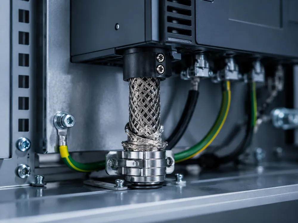
360° Clamp, EMC Gland or Pigtail: What Changes?
360° clamp or EMC gland
The shield is contacted around its circumference near the cable entry. This makes a broad, short connection and keeps the unshielded section small. It is the common arrangement where the drive or motor documentation calls for a 360° shield connection.
Short permitted pigtail
Some product instructions allow a short flattened or twisted shield connection where a full clamp is not available. It should not be silently substituted for a required clamp, and it should not be extended into a convenient long tail routed through the enclosure.
Shield left floating
An unconnected screen cannot perform the expected shielding function. This is often found after cable replacement, panel modification or a local enclosure where the installer treated the braid as unused material.
Shield landed on a convenient 0 V
A DC reference is not automatically the correct functional-earth or screen point. That choice can change signal behaviour and create an unintended coupling path. Use the designated connection point shown by the system documentation.
The Local Disconnect Is an EMC Checkpoint
A local motor disconnect or service box may meet the switching and maintenance requirement yet still break the VFD screen path. The phase conductors may be switched correctly while the screen is cut back, left floating or turned into a long pigtail.
Check the actual enclosure: cable entries, clamp points, bonding hardware and the recommended method for the drive system. The screen may need a 360° bond inside the disconnect, a screened pass-through or another defined connection. A PE terminal alone does not prove screen continuity.
Check three paths independently: the disconnect must meet its switching and isolation duty; PE must remain continuous; and the motor-cable screen must follow the required EMC connection. Combining all three at one green/yellow terminal often leaves the noise path unresolved.
Trace the screen from the drive output clamp to the motor end. Where it passes through a disconnect or service enclosure, identify the bond point, any exposed braid and the method used to continue the screen path. Compare the installed arrangement with the drive-system instructions rather than assuming the PE terminal provides the required EMC connection.
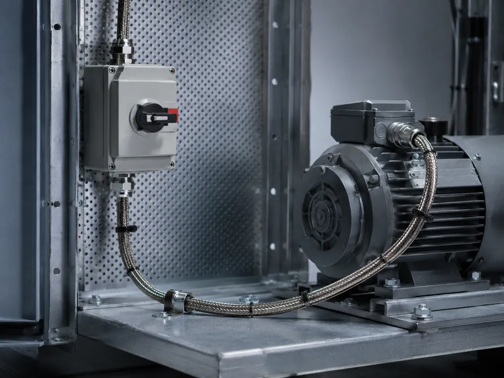
Control, Analogue and Encoder Cables Need Their Own Rules
| Cable type | Why a generic “both ends” answer can fail | What to verify instead |
|---|---|---|
| 0–10 V / 4–20 mA / small analogue signal | The screen may reduce interference yet also see low-frequency current where the endpoints are at different potentials. | Drive or I/O manual, cable construction, reference scheme, signal isolation, the stated screen endpoint and route away from motor output. |
| Digital control or safety-related low-voltage cable | Screening, pair twisting and separation can be more relevant than copying a motor-cable termination method. | Product requirements, voltage class, signal grouping and any prescribed functional-earth connection. |
| Encoder / resolver feedback | Feedback quality can depend on the encoder’s isolation from the motor and earth, plus the interface module design. | Drive, encoder and feedback-interface manuals together; cable type, individual pair screen, screen endpoints and connector or clamp arrangement. |
| Industrial communication | Protocol rules, connector shield contacts and equipotential bonding can be specific to the installed network. | Network installation guide, device manual and the actual topology. Do not substitute analogue or motor-cable guidance. |
For analogue and control signals, the question is not simply whether a screen exists. Check how the screen is connected in the system grounding scheme. One-end, capacitive high-frequency and both-end termination can each be correct in different circuits; the signal type and installed equipment determine the method.
Encoder feedback can fail intermittently after a cable or termination change. The fault may appear as a speed, position or parameter problem. Check the encoder cable, interface and screen connection before changing drive parameters.
Noise Symptoms: Follow the Coupling Path Before Replacing Parts
| Observed symptom | What it may indicate | First inspection points |
|---|---|---|
| Analogue value moves when the motor accelerates | Coupling into the signal route, a screen-endpoint issue, a shift between signal references or poor separation from motor output. | Signal cable type, pair shielding, endpoints, route, 0 V reference and any parallel run beside the VFD output cable. |
| Encoder fault appears only at higher speed | Feedback cable or connector issue exposed by drive output noise, movement or a change in screen continuity. | Encoder cable specification, interface termination, screen path, connector housings and motor-side arrangement. |
| Communication drops during drive switching | Network cable routing, connector shield contacts, reference/bonding arrangement or drive output proximity. | Network manual, shielded connector details, route crossings, cabinet bonding and changes made near the VFD. |
| Fault began after fitting a local disconnect or extending motor cable | The screen path, cable type, cable length or termination method changed during the modification. | Compare before/after route, disconnect enclosure, cable entries, clamp points, PE continuity and original manufacturer requirements. |
| Noise remains after replacing the drive | The system path may be in cable routing, motor connection, bonding or field wiring rather than the drive electronics. | Return to the full route: drive output, cable, intermediate enclosures, motor terminal box, control interfaces and screen terminations. |
Inspection Checklist for a VFD Shield Path
Specification wording that avoids ambiguity
Do not specify only “shielded VFD cable”. State the required cable type, screen termination, PE path and treatment of any local disconnect.
VFD motor cable: use the drive-approved cable type. Terminate the screen at the drive and motor ends using the method specified for the installed equipment. Keep the unshielded length at each entry within the specified maximum. Provide a separate, continuous PE conductor. Where the route passes through a local disconnect or intermediate enclosure, maintain the required screen connection and record the method on the drawing.
Related Reading
Common Questions
Should a VFD motor cable shield be grounded at both ends?
For a VFD motor cable, a low-impedance screen bond at both the drive and motor is common when specified by the equipment manufacturer. Check the approved cable type and the stated clamp or gland method.
Is one-end shield grounding suitable for an analogue control cable?
Sometimes. An analogue or control screen may be connected at one end, through an HF capacitor, or at both ends. Use the signal type and the drive or I/O instructions to choose the connection.
Is a drain-wire pigtail the same as a 360° shield termination?
No. A pigtail is a narrow conductor; a 360° clamp makes broad contact around the screen at the cable entry. Use a pigtail only when the equipment instructions permit it.
How should a local disconnect handle the shield of a VFD motor cable?
Treat a local disconnect as both a switching point and a screen-continuity point. Check whether the motor-cable screen must be bonded inside, passed through or re-terminated. Keep PE separate and continuous.
Are PE, FE and 0 V interchangeable shield termination points?
No. PE is the protective-earth conductor; FE is a functional earth or bonding reference; 0 V is normally the DC signal or power reference. Their links are defined by the system design. Do not land a screen on the nearest terminal.
What should be checked first when a signal fault appears only while a VFD is running?
Identify the affected cable, then inspect the screen path: clamps, unshielded tails, local disconnects, routing and the specified termination. Change one thing at a time so the source of the fault remains visible.